The Splat Board - NEW daughter board 2020
My Version of the Homebrew Lightning Detector (HBLD)
Note that as of October 2020 the Splat V1.0 daughter boards is available for the NECLEO STM32.
The Splat Board - NEW daughter board 2020
My Version of the Homebrew Lightning Detector (HBLD)
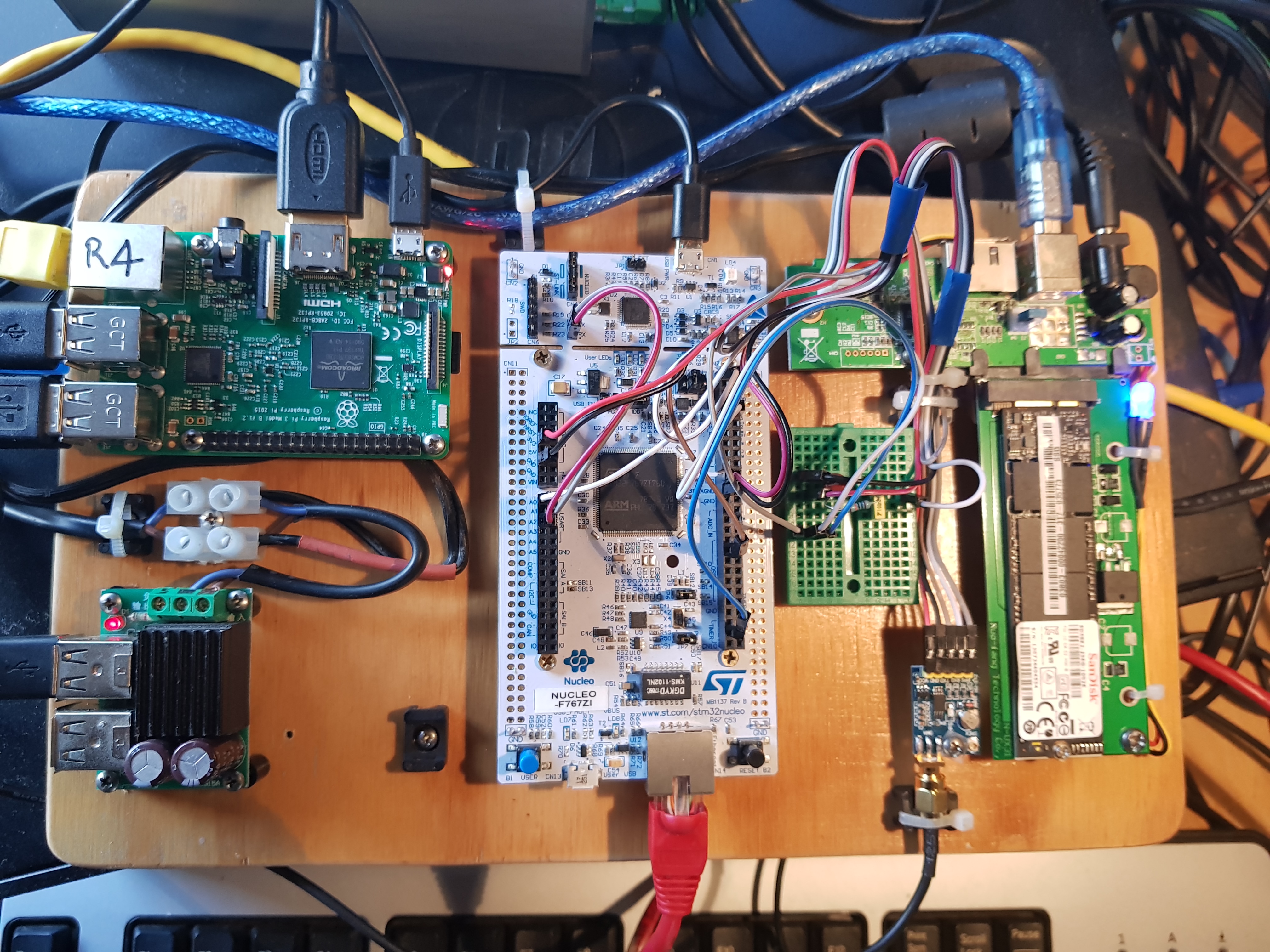
Bob VK4YA and Paul VK4PLY from the Bayside District Amateur Radio Society have been doing some excellant experimental work on lightning ground strike detection making use of a STM32F7 processor. They have undertaken this work independantly of the Blitzortung Project. Their objective is to obtain more accurate location of local strikes rather than world wide perspective. It is based on the Nucleo-144 demoboard, STM32 F767ZI and the Neo7 GPS unit. The project is in the early stage of development but they are making significant advances.
If monitoring and debugging is required then a Raspberry Pi is required to run a capture application with space on a sdcard to store data.
[Top][Home]
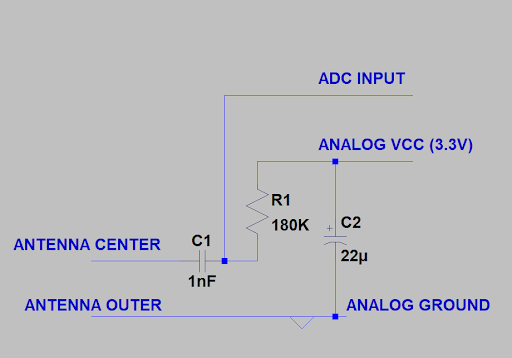
The antenna wire consists of a few meters of coax connected to the breadboard at one end as per the circuit diagram above, and then several meters of single wire. The unshielded part the antenna should be kept away from any source of electrical interference so false signal are not received.
[Top][Home]
A USB A to micro USB cable is required with the power and data lines connected.
Some USB cables do not connect the data pins as they are designed for charging
purposes only. So if the STM32 powers up but the USB device is not detected by the
OS try swapping out the cable.
Insert the USB cable into the STM32 and the Workstation or Raspberry Pi that is going to power the
STMM32. A filesystem should mount. The debug USB port is the micro port on the
J-Tag part of the STM32 board at the opposite end to the RJ45 network port.
My workstation detected the device in the system log as:
"New USB device found, idVendor=0483, idProduct=374b"
and mounted it in the Nautilus file manager as "NODE_F767ZI". It was 2.1Mbyte in size.
This usb port is also enabled as a modem serial port. It is seen as /dev/ttyACM0 on my Ubuntu
workstation.
[Top][Home]
Note:
The udev rule 49-stlinkv1.rules will be installed into /etc/udev/rules.d
The udev rule 49-stlinkv2-1.rules will be installed into /etc/udev/rules.d
The udev rule 49-stlinkv2.rules will be installed into /etc/udev/rules.d
The udev rule 49-stlinkv3.rules will be installed into /etc/udev/rules.d
This script will create the the Folder ~/Ac6 which contains the eclipse executable, and place an icon on the desktop that runs the application, "~/Ac6/SystemWorkbench/eclipse". As an alternnative, to the desktop icon launcher, the ac6 SMT32 workbench can be run directly from the "eclipse" binary in the the "~/Ac6/SystemWorkbench" folder.
The System Workbench toolchain, called SW4STM32, is a free multi-OS software
development environment based on Eclipse, which supports the full range of
STM32 microcontrollers and associated boards. Documentation can be found here:
http://www.st.com/en/development-tools/sw4stm32.html
[Top][Home]
Select the "Get Software" tab and accept the License Agreement.
Scroll to the very bottom of the page.
Sign in with youe email address and validate to start the download.
Save the file, en.stm32cubemx.zip in ~/packages/stm32cubemx
Installation Notes for Ubuntu 18.04.1 LTS:
Create a desktop icon by copying an existing icon and right-click to edit it properties. Update the form as follows:
| Name | STM32CubeMX |
| Description | STM32CubeMX for STM32 configuration and initialization C code generation |
| Command | /usr/local/STMicroelectronics/STM32Cube/STM32CubeMX/STM32CubeMX |
| Comment | STM32CubeMX for STM32 |
Update the icon by click on icon in properties window. Use the icon file:
"/usr/local/STMicroelectronics/STM32Cube/STM32CubeMX/help/STM32CubeMX.ico"
Run the STM32CubeMX and select File->New Project and select the file "~/packages/my9/my8.ioc".
You will then be asked to Download missing components or Migrate. Select Download
The application will then download selected software packages and automatically install them:
The installation of STM32CubeMX is now complete. See the Build Procedure Section
of this document to build the Homebrew Lightning Detector project.
As background documentation here is a PDF titled "Data brief - STM32CubeMX - STM32 configuration and initialization C code generation":
http://www.st.com/content/ccc/resource/technical/document/data_brief/7a/81/a9/b5/72/99/4b/be/DM00103564.pdf/files/DM00103564.pdf/jcr:content/translations/en.DM00103564.pdf
[Top][Home]
FreeRTOS is a Real Time Kernel (RTOS) for micro processors.
The FreRTOS Site's Home Page:
https://www.freertos.org/FreeRTOS-Plus/FreeRTOS_Plus_TCP/index.html
Download the file "FreeRTOSv10.1.1.zip" from the Sourcefourge download site
https://sourceforge.net/projects/freertos/files/latest/download?source=files and save it in to ~/packages/RTOS.
RTOS employees lwIP, a widely used open source TCP/IP stack designed for embedded systems.
lwIP was originally developed by Adam Dunkels at the Swedish Institute of Computer Science and is
now developed and maintained by a worldwide network of developers. lwIP is used by many manufacturers
of embedded systems.
Source Wikipedia: https://en.wikipedia.org/wiki/LwIP
[Top][Home]
Installing the git package is the simplest of all the software require to
support the Home Brew Lightning Detectors:
[Top][Home]
Please ensure all the prerequisite software packages have been sucessfully installed as
describle above in the Software Platforms. That is, The ac6 STM IDE, the STM32CubeMX code
generator, FreeRTOS, and git utilites.
Firstly obtain the source code. The HBLD source code is archived at guthub site, in the my9 repository,
and can be accessed with this link:
https://github.com/bobwis/my9.
Note that the source is case senitive on linux, and case insensetive on Windows.
I installed the source in the ~/packages folder from the git repository
using "git clone" or "git pull", Alternatively, copy the link and download full archive.
The my9 respositary contains full source to the application that runs on the HBLD STM32.
If no changes have been made to the project code locally, or you are starting from scratch,
download a fresh copy of the source. It is safer to remove the my9 folder and clone it from
scratch, in case some intermediate files have not archived correctly.
NOTE: Do not delete my9 if you have made local changes to the source code.
Download the source:
Alternatively, update the source with the following github commands:
As a precaution, backup the project file my9.ioc:
[Top][Home]
The STMM32MXCube will not compile with assistive technology classes so edit this file to remove them.
The java Runtime version I am using on Ubuntu 18.04.1:
[Top][Home]
This is the Linux open source, command line version of the of the STMicroelectronics Stlink Tool.
It is used to load firmware over the USB port to STM processor boards.
The install procedure can be found here:
github Archive of the Open STM32 Firmware and Debug Tool (local).
This stand alone tool is not necessary as similar mechanisms are included in the Ac6 Eclipse Intergerated Development Enviorment (IDE).
http://www.pilotlogic.com/sitejoom/index.php/codetyphon
http://www.pilotlogic.com/sitejoom/index.php/downloads/send/14-codetyphon/123-codetyphonins-zip
http://www.pilotlogic.com/sitejoom/index.php/downloads/send/16-linux/131-arm-linux-pi-7z
CodeTyphon has an extensive, multistage, and somewhat tiresome installation process. It begins with an character
based installation, and a graphical build of the IDE. Finally, you get the IDE product to work with.
Select "0" to start the install process.
Select "0" again to download and "Install System Libraries". This install a lot of apt packages.
Keep repeating the install until all package required are downloaded and installed and you get
a message like this:
Option 11:
CodeTyphon Studio Unix Platform (widget) Setup
        Current Platform: gtk2
Option 12:
   CodeTyphon Studio Multi-Architecture Setup
      Current Multiarch Mode: 1

   0) NO  Multi-Architecture Mode (Multiarch=0)
   1) Use Multi-Architecture Mode (Multiarch=1)
I had difficulty running CodeTyphon from the icon as it would stall on most menu options.
I assume this is a permission problem . There appears to be a problem in the ways the application
nneds to gain sudo status or maybe permissions are not correct.
The solution is to start CodeTyphon the "sudo ./install.sh" command, but warns against have "root"
privledges.
Next, Select 1 to Run CodeTyphon Center (CTC) and Select Menu Item "Typhon-->Build BigIDE" to build the BigIDE.
This can take a long time. Select the "CommandBox" tab to view the progress.
After all this processing CodeTyphon creates a new application IDE called "Typhon64"
and a new desktop icon to go with it.
Typhon's working directory is /usr/local/codetyphon/typhon/
Now refer to the build section to compile the data relay application "captofile1".
Build the Data Relay Application "captofile1"
CodeTyphon makes extensive use of MESA for its Graphical User Interface.
Mesa, also called Mesa3D and The Mesa 3D Graphics Library, is an open
source software implementation of OpenGL, Vulkan, and other graphics
specifications. Mesa implements a cross-language, cross-platform,
vendor-neutral standard API for translating these specifications to
vendor-specific graphics hardware drivers.
Source Wikipedia:
https://en.wikipedia.org/wiki/Mesa_(computer_graphics)
In Greek mythology, Typhon was a monstrous serpentine giant and the
most deadly creature . According to Hesiod, Typhon was the son of Gaia and Tartarus.
Typhon and his mate Echidna were the progenitors of many famous monsters. Typhon
attempted to overthrow Zeus for the supremacy of the cosmos. The two fought a e
cataclysmic battle, which Zeus finally won with the aid of his thunderbolts.
Defeated, Typhon was cast into Tartarus, or buried underneath Mount Etna,
or the island of Ischia. Hopefully, the software does not reflect it's namesake.
Source Wikipedia:
https://en.wikipedia.org/wiki/Typhon - Wikipedia
Firstly make sure the Typho64 IDE is fully installed.
See the section above: Building the CodeTyphon IDE
The Captofile CodeTyphon build requires ttf-mscorefonts for the screen layout to look well
proportioned. The MS true type fonts can be install with the apt utility thus:
Copy the "Captofile1" source file into th3 ~/packages/captofile folder.
I had to change ownership of these folders to get typhon to run properly.
Note I had to remove "{$IFDEF WINDOWS}mmsystem{$ELSE}" condiftional from the source file.
The Linux do not support the Microsoft multimedia system libaries.
Typhon64 places the compiled executable in:
/usr/local/codetyphon/typhon/Captofile1/lib/x86_64-linux/captofile1
and a ARM binary suitable for execution on the Raspberry Pi placed in:
/home/glenn/packages/captofile/Captofile1/lib/arm-linux/captofile1
It is more convient to copy the executable to a local folder.
The captofile1 program will create a captofile1.ini file the first time you attempt to save any
configuration, so do not install it in "/usr/local/bin" as normal users do not have priveldges
to create files in that folder. I chose to make a bin folder in my home folder.
[Top][Home]
If you wish to build the stock standard version of the HBLD skip this process. The chip level includes
are already included in the my9 source code downloaded from the repository. It is only necessary
to run the STM32CubeMX if you wish to make changes at the hardware level. EG interupts, DAC, ADC, etcera.
The second task to building the firmware is the STM32CubeMX code generator.
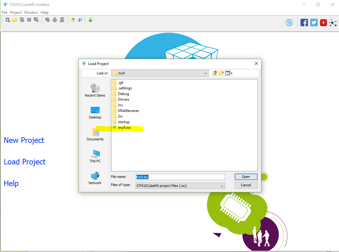
Run up the STM32CubeMX IDE from the icon created on the desktop and open the .ioc project file.
Select File->Load Project and choose ~/packages/my9.
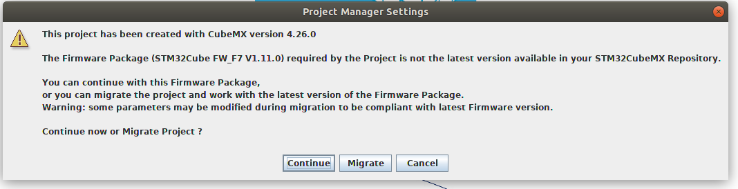
If the developemnt version in my9 is not the latest STM32cubeMX, you will be presented with this
screen:
 .
.
Th safest course is to select "Continue". "Migrating" is desirable but may lead to configuration issues.
The startup screen will take afew minutes to appear:
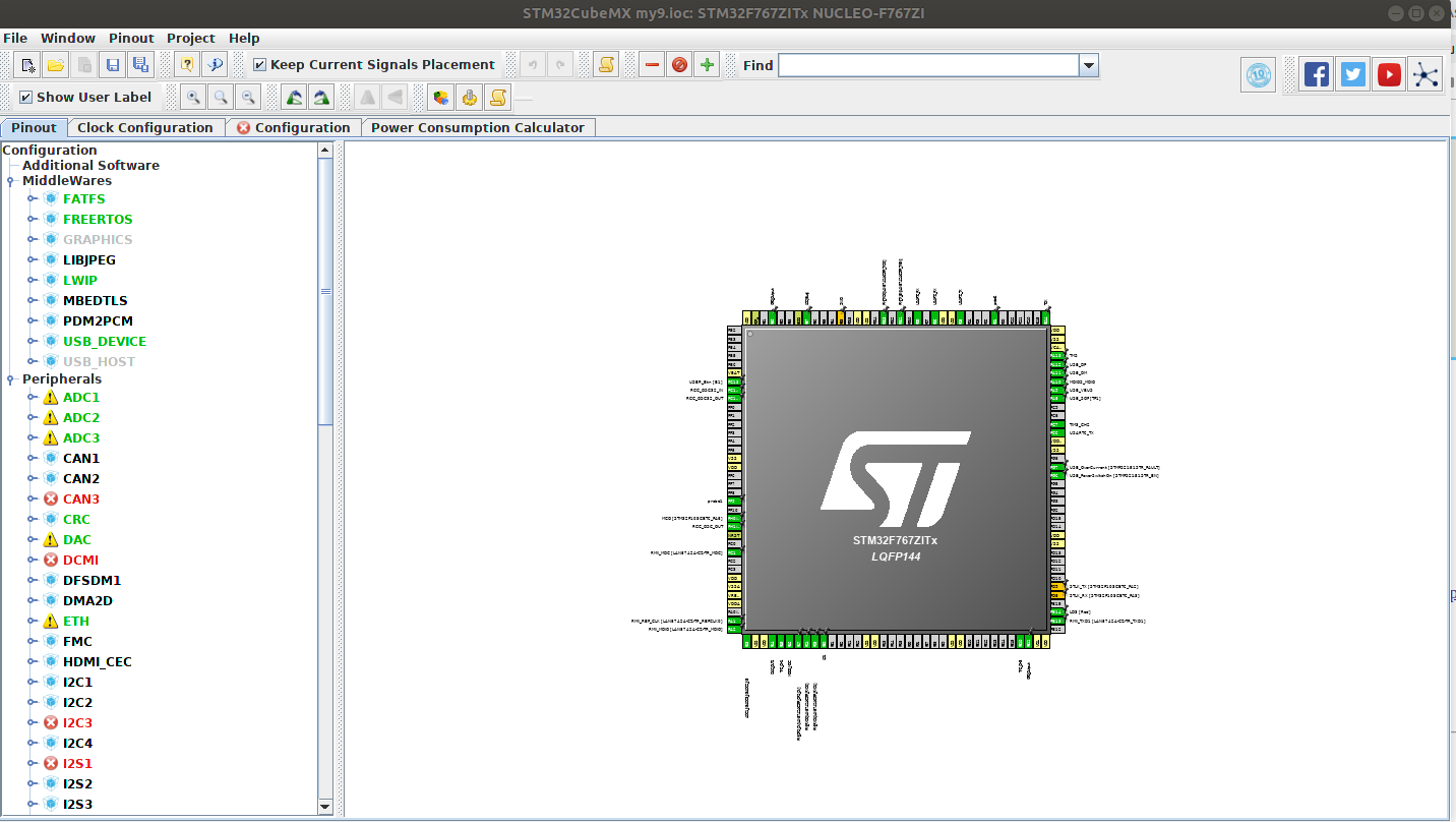
The red labels indicated that those peripherals and pins have been allocated and are no
longer available for use. They do not indicate an error condition.
Select the code generator option with the menu bar icon
![]() .
.
SMT32CubeMX automatically generates include files into the my9 project area, ~/packages/my9.
Most of these are included into "main.c". STM32MX will then offer to start the STM32 Workbench.
You can proceed directly to the workbench or exit The Code Generator and start the SMT32 workbench
by executing "~/Ac6/SystemWorkbench/eclipse" binary.
Note that there are two files that do not automatically get included and
have to be copied manually. They are:
Middlewares/Third_Party/LwIP/src/apps/httpd/fs.c
Middlewares/Third_Party/LwIP/src/apps/httpd/fsdata.c
If you forget to copy thess two files you will get fatal compiler error: fsdata.c: No such file or directory.
[Top][Home]
There are a couple of manual edits that are required to the my9 source.
Start the SMT32 Workbench if it not already runing. If this is the first tiome it has been runing
In the STM32 System Workbench
Two file require manual editing.
Edit the version.h file and change
#define MY_UID "1099" to your serial number.
and change the testing flag
#if 1
#define TESTING
#endif
Make sure it is set to "1" if you wish to test or set to "0" for production.
Edit the udpstream.h file and change
#define SERVER_DESTINATION "lightning.vk4ya.space" to your local IP address
if you wish to run the cptofile1 relay application instead of sending the packet data directly to the
server.
[Top][Home]
As an alternnative the ac6 SMT32 workbench can be run from the "eclipse" binary in the the "ac6" folder.
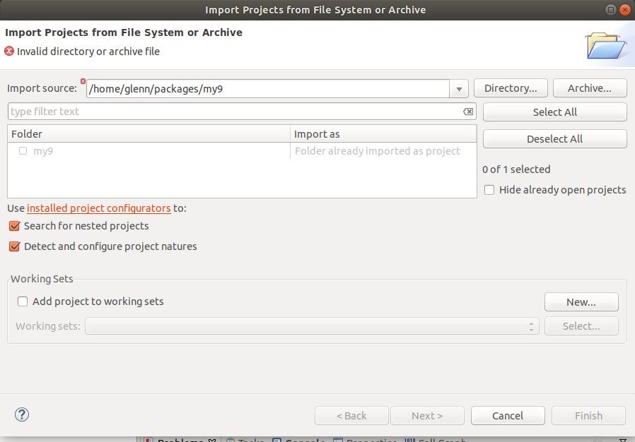
Select ~packages/my9 and "Finish"
The source will load in to the Eclipse STM32 workbench.
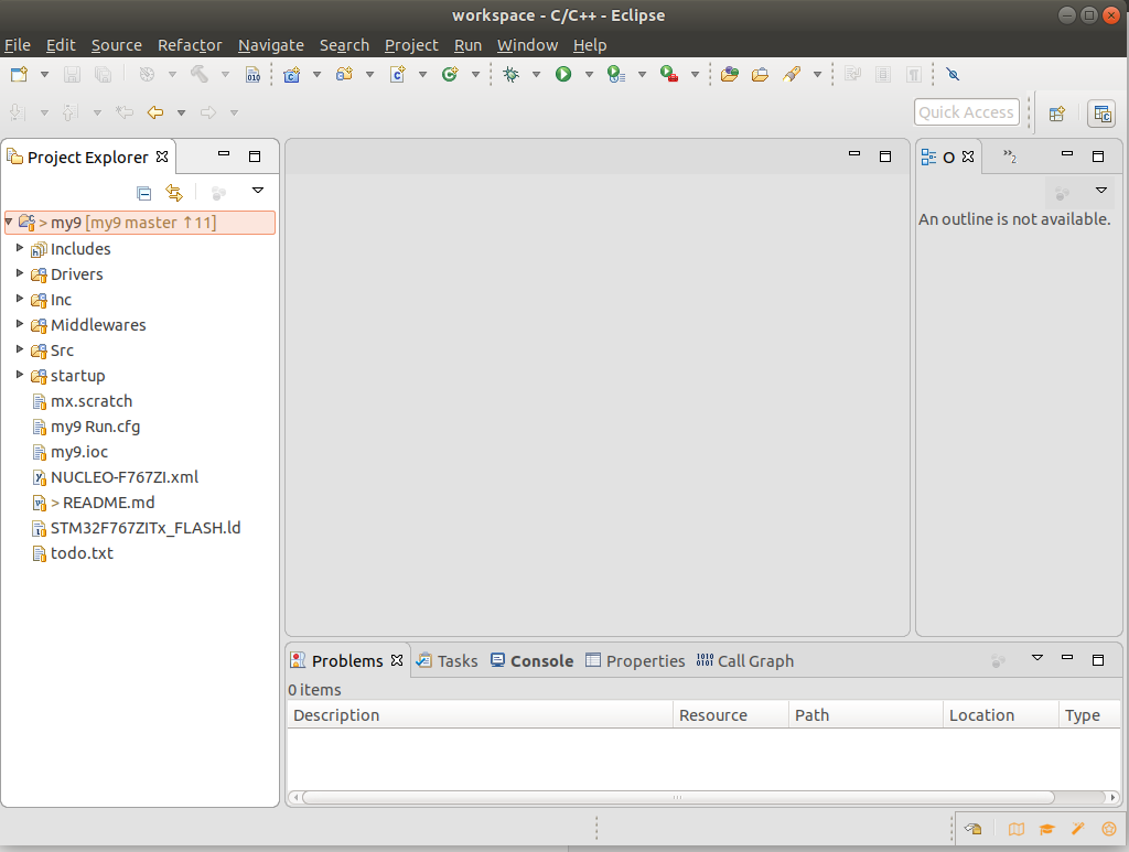 The imported my9 source archive
Point it at the top directory where my9 is located. The my9 will display in the
project explorer pane on the left hand side.
The STM32 Jtag USB port (which also powers the STM32 in normal cases) must be connected
to a USB port on the same platform (Windows, Linux Workstation, or Raspberry Pi)
Use File-->Open to open the Project from File System in STM System Workbench,
Select "Build All"
[Top][Home]
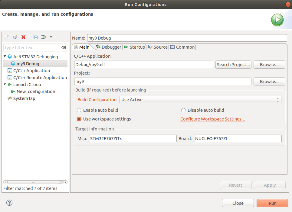
If set up correctly the STM32SW will load the compile and load the firmware into the STM32 board.
In the STM32SW IDE navigate to:
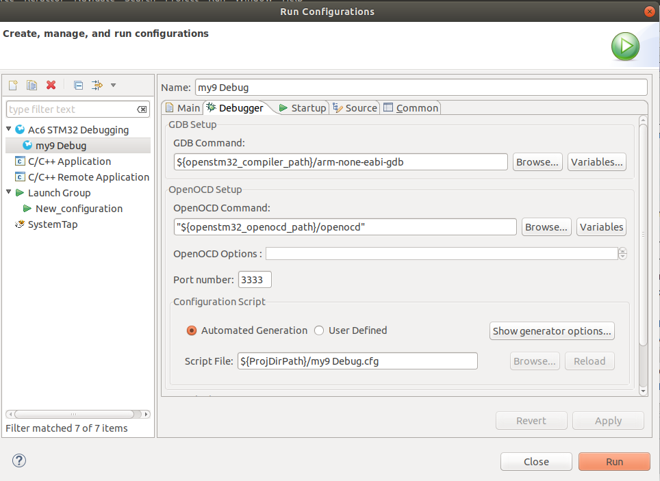
The second tab details the debugger tools to be used. Nothing needs to be changed. The GBD Command
is set to use "arm-none-eabi-gdb" and the OpenOCD Command is set to use "OpenOCD"/
The "Open On-Chip Debugger" provides JTAG/SWD access from GDB (or directly with TCL scripts)
to processors with ARM and MIPS based cores.
As an alterntive to compiling the source code a binary can be downloaded and installed.
There is a binary of my9.bin on github. This binary version can loaded directly onto
to the STM32 lightning server.
Make sure the USB cable is correctly plugged into the Ubuntu workstation and the STM323
as described in the hardware Section of the document:
The USB Connection for Power and Communication
Remember, The debug USB is the micro port at the opposite end to the network port.
Once this is done press the black reset button on the STM3 to load the binary and output the
strtup dialogue to the serial port.
Note:
Either copy over shared usb drive or use the compile and run option in the IDE -
as long as USB is connected to your PC
Its the 'Run' option in the IDE menu. Also the Green Right Arrow Icon when its
learned it after the first go. The 'bug' icon is 'run' and debug.
To building the target software for the STM, you do not need to download LWIP or
FreeRTOS. They were installed by the STM build system. I'm guessing it was the
STM32CubeMX 'front-end' code generator that brought it in (but it could have been
the STM32SW IDE). There is a my9.ioc file that the STM32CubeMX generates into the my9 project
folder that show all the dependencies.
On the STM32SW IDE, the version.h file contains a directive for TESTING or not. All this does
is set the status packet rate to once a second rather than once every two minutes,
also, it also sets the IP Address (or DNS name) afrogots defined in a conditional test found
in udpstream.h.
The green LED on the STM32 should flash every second when the GPS is
sending the one pulse per second (1PPS).
The black button on the STM board is the reset.
Source:
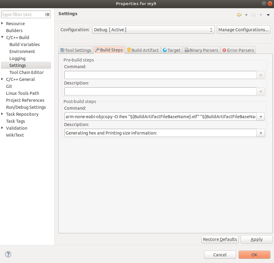
In the STM32SW IDE navigate to:
Change:
arm-none-eabi-objcopy -O ihex "${BuildArtifactFileBaseName}.elf" "${BuildArtifactFileBaseName}.hex" && arm-none-eabi-size "${BuildArtifactFileName}"
to
"arm-none-eabi-objcopy -O binary" "${BuildArtifactFileBaseName}.elf" "${BuildArtifactFileBaseName}.bin" && arm-none-eabi-size "${BuildArtifactFileName}"
[Top][Home]
Configuring the Data Relay and Monitoring the System (Captofile)
My advice would be to change TESTING to 0, and to uncomment the SERVER_DESTINATION
in udpsream.h which has "lightning.vk4ya.space" as the target. You will also have
to comment out the existing entry in that 'else' clause. Recompile and run will
update the STM board with the new firmware.
After that it should be running and sending to the server directly, with status
packets every two minutes. You can open a serial terminal on the USB port to see the
start-up messages and any subsequent errors:
To see the output data in the 'Capture' program on the RPi, just change that SERVER_DESTINATION
entry to point to the local RPi IP address.
On the RPi run he Captofile program from a bash shell and and every two minutes you
should see the status field update (and the sample packet field when it detects an
event).
The Options tab in the Sample program lets you relay the packets on to the server
as well. (see Screenshot below), so you can run Capture and still send the data to
the Server.
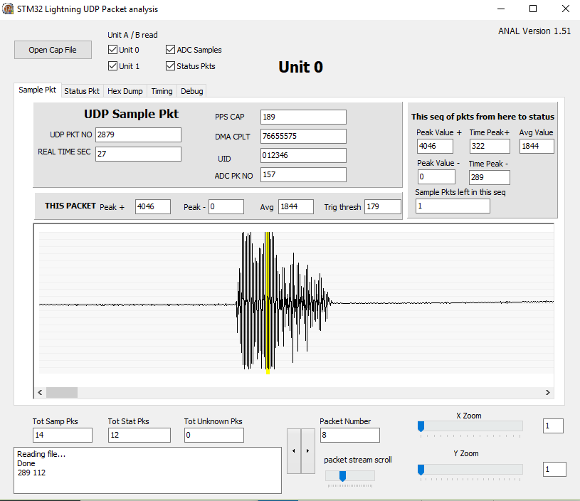
The Captofile program will eventually fill up a file Raw3.bin on the RPi, (but it
should take weeks to break the filesystem). The Raw3.bin file can be read into
another program named 'Anal1' to display the samples, waveforms etc and the captured
packets. Its very CPU intensive so it is not ported to the RPi. It compiles
on Windows and Ubuntu PC's using Typhon.
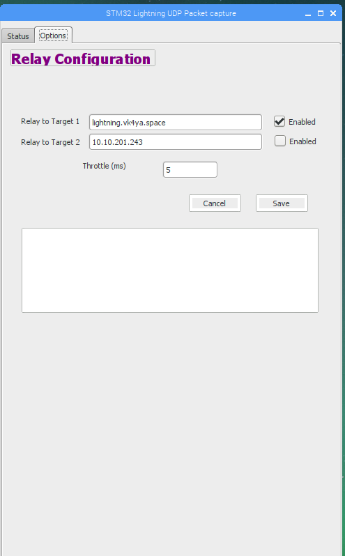 Relay Configuration Screen - Relay data to lightning.vk4ya.space (112.213.32.44)
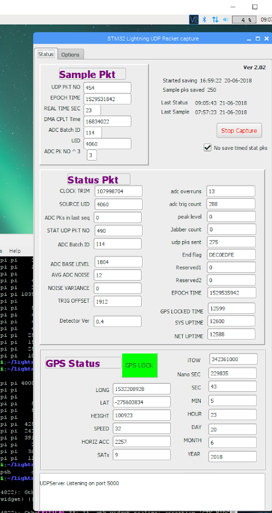 Packet Capture Monitor and GPS Status Screen
[Top][Home]
Loading the Binary Version
Downloaded the binary from github:
https://github.com/bobwis/my9/blob/master/Debug/my9.bin
Insert the USB cable into the Ubuntu workstation and a filesystem should mount.
The debug USB is the micro port at the opposite end to the network port
My workstation detected the device in the system log as: "New USB device found, idVendor=0483, idProduct=374b"
and mounted it in the Nautilus file manager as "NODE_F767ZI" and was 2.1Mbyte in size.
Copy the my9.bin file into the shared 2MByte drive offered by the STM32 and initate a
reboot to load the binary.
[Top][Home]
Monitoring the Serial Port
You will need a serial port communications program. Cutecom is a graphical serial port
communications program, similar to the character based Minicom.
It can be loaded with the apt utility:
The system log, dmesg shows that /dev/ttyACM0, the USB ACM device, is active.
Open the serial console to the STM32 in cutecom to see the startup dialogue.
Add Cutecom to the favourites menu.
Configure Cutecom:
The startup dialogue will display serial numbers and IP addresses as it boots.
You can now assume you have a live lightning detector that sending packets to the server.
Note that this dialogue is only active during the startup process.
[Top][Home]
Viewing The Results
http://s7.slashdit.com:8080/detectors
[Top][Home]
MTU and the UDP Fragmentation Issue
Some moden do not allow for the resetting of the Maximium Transfer Unit, MTU.
https://support.microsoft.com/en-au/help/314496/the-default-mtu-sizes-for-different-network-topologies
I've confirmed that the STM LwIP fragmenting the packets is too much for its little brain,
and it can't keep up with the ADC. So after much googling I think I've found a solution
to keep your detector sending full size packets without any new software (so use the last
version you built).
The trick is to point your detector at the RPi as per normal, run the Capture program to
relay the packets to the server, but firstly run this command on the RPi:-
ip route add 112.213.32.44 via
[Top][Home]
Frequently Aasked Questions
The Red LED and Blue LED flash when a detection event occurs.
An event can be simulated by ckicking a pizo lighter (or placing a finger on the antenna/ADC input pin).
[Top][Home]
Glenn Lyons VK4PK
glenn@LyonsComputer.com.au
Ver:gnl20180914 - pre published v0.9