Official Product of Scott Zimmerman / Repeater Builder
Inspired from a similar design: github.com/wojciechk8/MMDVM_pog
Low-pass filter design by SQ6POG
Images property of Repeater Builder.
Logo Design by Elisha Zimmerman KB9WCX
HTML June 17, 2017 - N3XCC
[Top][Home]
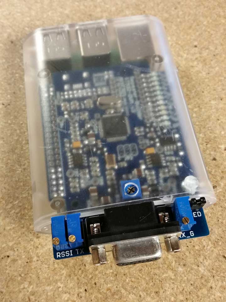
There are two chains of low-pass filtering. (One for TX, one for RX) These filters are a 3 pole filter with a "knee" of approximately 4kHz. There is a 25 turn potentiometers for fine Receive and Transmit Audio level adjustment. and a DB-9 connection to the host repeater. RSSI support built on-board, as well as 'clip' circuit to help with RX level adjustment.
Link to the Version 3a (Blue) Schematic and Board Layout of the STM32-DVM.(local)The FT230X is a USB to serial UART interface with optimised pin count for smaller PCB designs.
https://pdf1.alldatasheet.com/datasheet-pdf/view/603503/ETC2/FT230XS.htmlARM's Serial Wire Debug (SWD) replaces the traditional 5-pin JTAG debug interface by introducing a 2-pin interface with a clock (SWDCLK) and a single bi-directional data pin (SWDIO), providing all the normal JTAG debug and test functionality, anyhow dayisy-chaining devices as via JTAG is not possible. SWDIO and SWCLK are overlaid on the TMS and TCK pins, allowing to use the same connector for JTAG and SWD. In order to communicate with a device via SWD, data is send on SWDIO, synchronous to the SWCLK. With every rising edge of SWCLK, one bit of data is transmitted or received on the SWDIO pin.
Jumper J3 has six pin for the Serial Wire Debug connectorThere are two variants of the SSD1306 display, one running on SPI bus and the other on I2C. f5uii discrible how to install the i2c variant.
https://www.f5uii.net/en/installation-oled-display-ssd1306-raspberry-pi-mmdvm-mmdvmhost/Probably the easiest way t do the is using a USB to Serial Converter. See link below.
https://www.ailunce.com/blog/Update-Nextion-Display-for-Pi-Star-MMDVM-DMR-Hotspot