| Link | Function | Options |
|---|---|---|
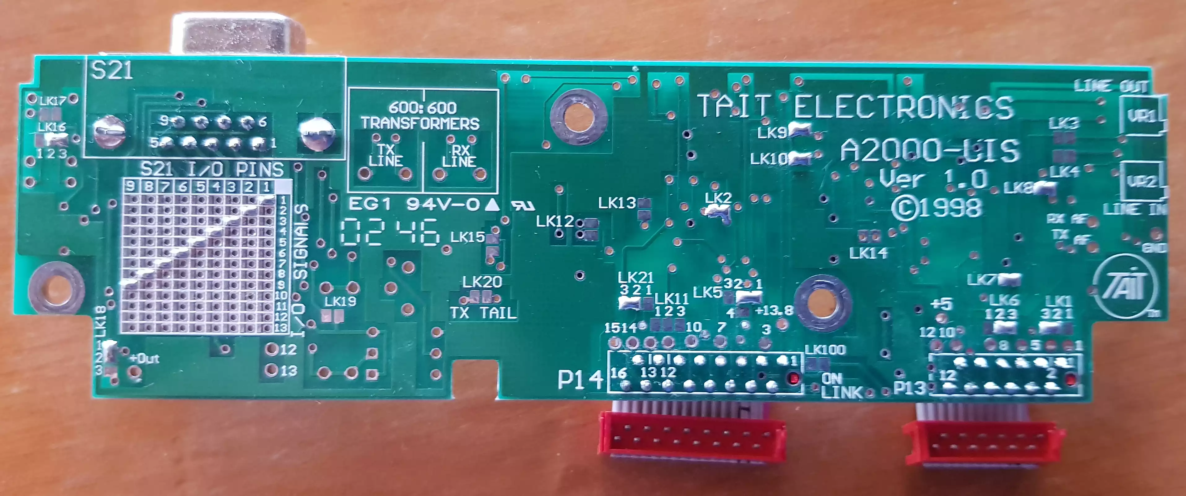
| LK1 | LINE OUT Flat / De-emphasised | 1-2 Flat / 2-3 De-emphasised |
| LK2 | MIC AUDIO to LINE OUT | IN = YES / OUT = NO |
| LK3 | BEEP to LINE OUT | IN = YES / OUT = NO |
| LK4 | LINE IN to LINE OUT Side Tone | IN = YES / OUT = NO |
| LK5 | GATE OUT Source | 1-2 BUSY + RX GATE 2-3 BUSY ONLY 2-4 TRUNKED BUSY |
| LK6 | LINE IN Flat / Pre- emphasised | 1-2 Flat / 2-3 Pre-emphasised |
| LK7 | LINE IN to Volume & Speaker | IN = YES / OUT = NO |
| LK8 | LINE IN Flat / Pre- emphasised | IN= Pre-emphasised / OUT = Flat |
| LK9 | LINE IN 1 600 Terminated | IN = YES / OUT = NO |
| LK10 | LINE IN 2 600 Terminated | IN = YES / OUT = NO |
| LK11 | LINE OUT, LINE IN, GATE OUT and PTT IN Control | OUT = NONE 1-2 AUX SW 2-3 CALL SW |
| LK12 | RX/TX Disabling | IN = YES / OUT = NO |
| LK13 | RX Disable | IN = TX ONLY/ OUT = NO |
| LK14 | GATE OUT Phase | OUT = Active Lo / IN = Active Hi |
| LK15 | PTT IN Phase | OUT = Active Lo / IN = Active Hi |
| LK16 | GATE OUT Relay Phase | 1-2 N.C. / 2-3 N.O. |
| LK17 | GATE OUT Common to Ground | IN = GROUNDED / OUT = NOT |
| LK18 | I/O Signals matrix line 11 - Volts Source | 1-2 +13.8V SW / 2-3 +13.8V UNSW or OUT = NONE |
| LK19 | OPTO Coupler Option | IN = Yes / OUT = NO |
| LK20 | TX Tail Timer | IN = Yes / OUT = NO |
| LK21 | External Line Source | 1-2 /Emrgncy / 2-3 RX/TX Disabling |
| LK22 | LINE OUT 1 output impedance | IN = Very Low / OUT = 600 OHMS |
| S21 Pin | Signal |
|---|---|
| 1 | LINE OUT 1 |
| 2 | /GATE OUT 1 |
| 3 | GROUND |
| 4 | /PTT IN 1 |
| 5 | LINE IN 1 |
| 6 | LINE IN 2 |
| 7 | /PTT IN 2 |
| 8 | /GATE OUT 2 |
| 9 | LINE OUT 2 |
| S21 Pin No. | Signal | Description |
|---|---|---|
| 1 | OPTO-IN | Input for external opto coupled line current detector. +8V logic. |
| 2 | OPTO-OUT | Output to drive external opto coupled line current switch. 1k ohm series resistor for LED. |
| 3 | +8V-OUT | +8V output to supply external opto coupled line current detector. |
| 4 | +13.8V-OUT | Unswitched +13.8V output to provide an unisolated keying supply. |
| 5 | LINE-OUT | Output audio path to transmission line or transformer. |
| 6 | KEYING | Bi-directional key line for use with simple two wire linking (optionally linked to OPTO-IN internally). +8V logic. |
| 7 | BCD0-OUT | Inputs used for 4 channel remote switching with the T2010. +5V logic. |
| 8 | BCD1-OUT | |
| 9 | Spare | Decoupled uncommitted line. |
| 10 | GND | Options ground. This is earth derived from the regulator section of the T2000 main PCB. Used to avoid earth loop noise. |
| 11 | PTT-IN | Keys transmitter and operates line control logic. Trunking PTT selectable. +5V logic, sense selectable by links. |
| 12 | BUSY/GATE | Busy or Rx gate output. Trunking busy link selectable. +5V logic, sense selectable by links. |
| 13 | IN-LOCK-OUT | Synthesiser lock detector output. +5V logic, sense selectable by links. |
| 14 | TX/RX-OUT | Tx regulator control output. Indicates whether the radio is in Tx or Rx. +5V logic, sense selectable by links. |
| 15 | LINE-IN | Input audio path to transmitter audio stages. Normally linked to LINE-OUT for a bi-directional line but is able to be separated for other applications using two transmission lines. |
| - | CGND | Provided via S21 D-range and cable screen if required for RF susceptibility. |