VK4MWL Remote HF
Contents:
- Github Repository
- Kicad Installation
- Node-Red
- Possible Enhancements
- Schematic
- Bill of Materials
- Considerations for the Gas Dischard Tubes
- Errata 1
- Errata 2
- Construction Photographs
[Top][Home]
Testing
Ran a 100W through the board into a dummy load. No issues with SWR 160m to 6m.
[Top][Home]
Github Repository
Remote HF PCB and Node Red Website for WFView, SteppIRAntenna and Yeasu Rotator:
git clone https://github.com/mlanagan/RemoteHF.git
[Top][Home]
Kicad Installation
Kicad V7.0 installation on Ubuntu:
https://www.kicad.org/download/details/ubuntu/
Alternatively, follow these inastructions:
The Interactive Html Bom tool Plugin is available here:
https://github.com/openscopeproject/InteractiveHtmlBom/wiki/Installation
- Download the source archive from the above site, and unzip to a temporary directory.
- Run up Kicad and select form the menu Tools -->External Plugins -->Open Plugin Directory.
- A directory will open, in my case it is "~/.local/share/kicad/7.0/scripting/plugins".
- Copy the unzipped directory, "InteractiveHtmlBom-master", into the directory.
- Then "Generate Interactive HTML BOM" will appear in the Tools menu.
- Generate a interactive BOM.
Add the this custom worksheet file vk4mwl.kicad_wks to this directory to create:
".local/share/kicad/7.0/template/vk4mwl.kicad_wks". Paste the following into the file.
[Top][Home]
Node-Red
Node-Red is required for software developemnt:
The Node-RED Platform
[Top][Home]
Possible Enhancements
- Next version could have an SWR bridge and automatically shut down the transmitter if the SWR is out for range.
- A connection for a dummy load.
- Given there is a Pi, an 8" colour LCD with some sort of UI
- Relays and I/O to control startup and shutdown of radio equipment such as transmitters and amplifiers.
[Top][Home]
Schematic
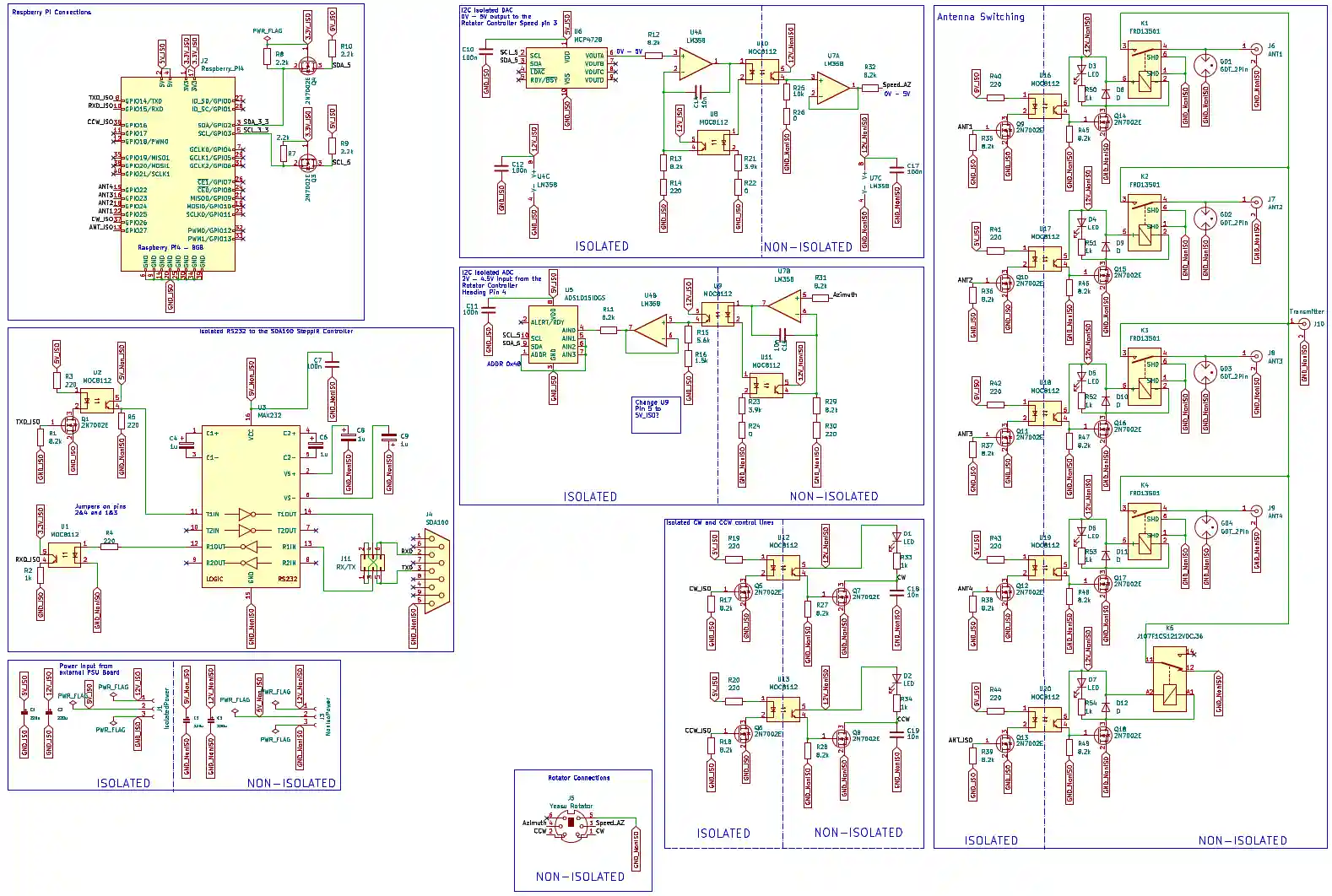
Source:
20230907-RemoteHF-Schematic.pdf
[Top][Home]
Bill of Materials
Remote Radio Control BOM [html]
[Top][Home]
Considerations for the Gas Dischard Tubes
2053 Series Light Duty 2-Electrode Miniature Gas Discharge Tube:
https://www.bourns.com/docs/Product-Datasheets/2053.pdf
The GDT on the antenna outputs come in 350/3Kv. Is this value the best choice?
[Top][Home]
Errata 1
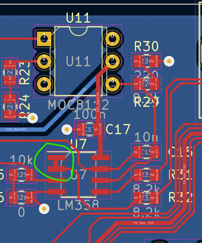
There is a link missing on the board between pin 1 and 2 on U7. A solder blob or jumper on those two pins
will be required.
[Top][Home]
Errata 2
The mounting holes on the raspberry pi side have no copper so they are isolated from the case.
Remove the solder mask with flat blade screwdriver so that the copper is exposed on the bottom side
for these four holes. This will link the case to the non-isolated ground and all the antenna
grounds through the case.
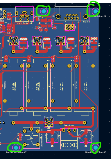
[Top][Home]
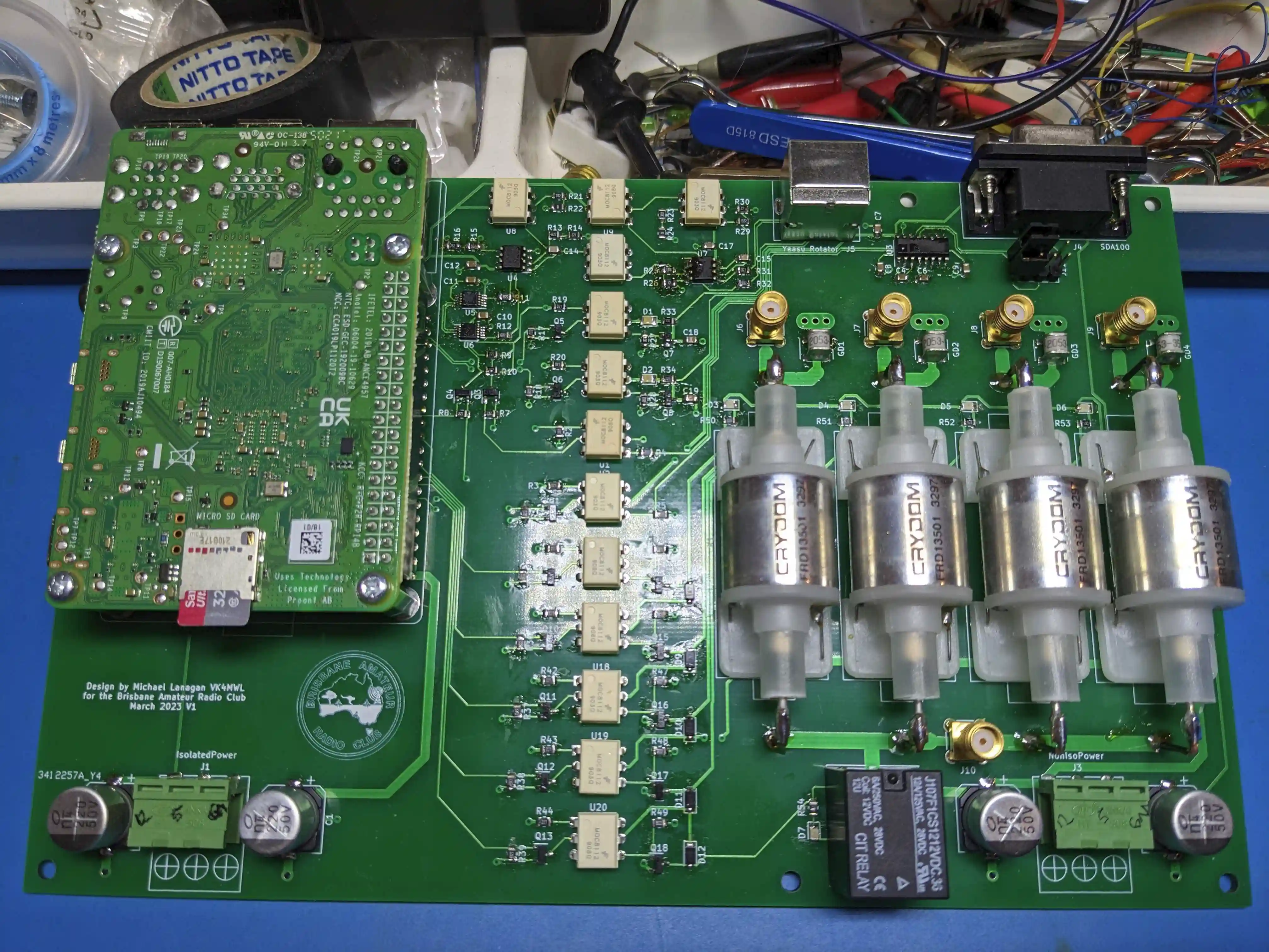
Construction Photographs
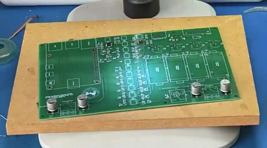
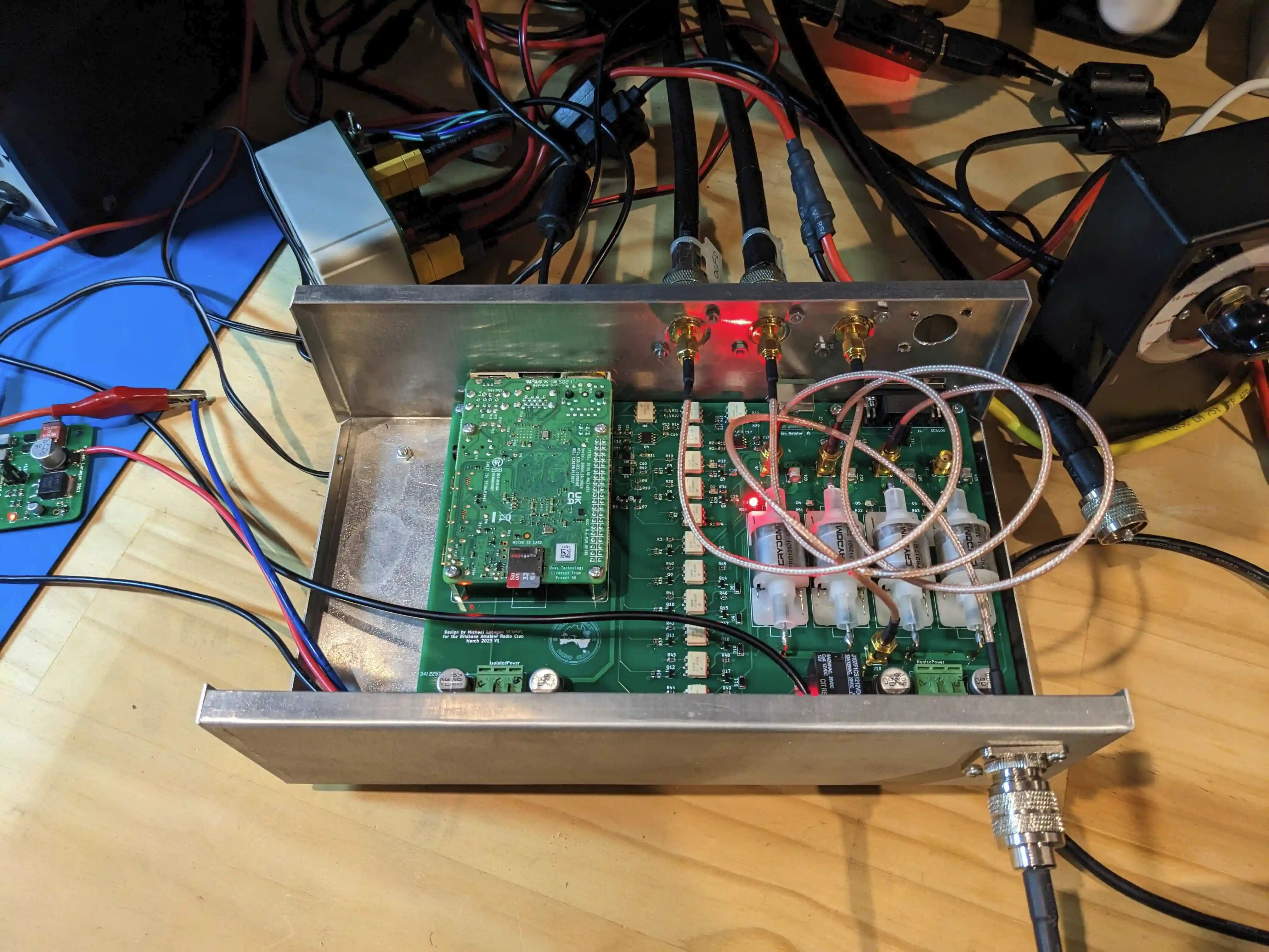
[Top][Home]
Glenn Lyons VK4PK
glenn@LyonsComputer.com.au
Ver:gnl20230625 - pre published v0.9