[Top][Home]
Option 0 - VK9XXX Station Identity and Facts
Descriptions of station, location, Licences Details, VK9XXX description, Conditions of Use for Remote Station[Top][Home]
Option 1 - Emergency Shutdown
This option will power down all radios and antenna relays. Assuming the power
connect them to 50 ohm dummy loads. We may also consider what other devices
should be power down (See Appendix A).
[Top][Home]
Option 2. - Select Radio to Operate
This will select a radio to manipulate. At this stage it will be one of two.Select Radio Menu:
[Top][Home]
Screen 1-2-1 - Radio One Menu:
Radio One Menu:[Top][Home]
Screen 1-2-2 - Radio 2 Menu
Radio 2 Menu:[Top][Home]
Option 3 - Station Status Menu
This Will be a quick check on all the network connected devices attached
to the remote facility. See Appendix A for currently planned devices and
Appendix B for possible other devices. This may be a as simple as a ping
command to the device and listen for the expected reply. This can be enhances,
in time, to check more thoroughly. Eg that certain processes are running
when resource permit. The Nagios application may be a suitable application.
Screen 1-3 - Station Status Menu:
[Top][Home]
Screen 1-3-3 - Antenna Status Report Menu
Screen 1-3-3 - Antenna Status Report Menu:[Top][Home]
Screen 1-3-3-1 - Antenna Status Report Ground Based Antennas
Screen 1-3-3-1 - Antenna Status Report Ground Based Antennas:[Top][Home]
Option 3 - Station Status Menu
Screen 1-3-3-1 - Antenna Status Report Tower Based Antennas:[Top][Home]
Option 3 - Station Status Menu
Screen 1-3-3-3 - Antenna Status Report Horizontal wire Dipoles:[Top][Home]
Option 4 - Station Status Menu
This will present a menu that allows for interrogation and manipulation of the
PDU with built in safety factors. Obviously, the network router used for control
and the control computer should be connect directly to power (not through the
PDU). All other should be able to be power cycled.
[Top][Home]
Option 5
Option 3 - Station Status Menu
Heart Beat Menu is to allow the setup of alerts for system failures or events
that need attention. This could be a connection to an one or more administration
computers. It could be a system of SMS messaging that sends text messages via
an external SMS messaging service. This facility should allow the selection
of individual events to be monitored or not and the maybe the time interval
[Top][Home]
Option 6 - Book a time slot on a Radio
A booking system is highly desirable. Some form of calendar that allows time
slots to be allocated to users. Google Calendar may be a suitable candidate.
See https://developers.google.com/calendar/quickstart/python
This requires a user the have a google account. There are advantage to using
google Calendar as it will handle a lot of the user interface via a separate
Web based login.
Booking will be for a maximium of one hour but can be booked for less time.
If a booking is not utilsise for 10 ten minute after the booked than it is
forfieted and becomes available for standby.
The Standby list is only available for a 24 hout period and is mainatained on
a first come first served basis. (FIFO) If the standby booking is not taken up
within 5 minutes the remining time will roll to the next member in the list.
Calendar Functions
- Make/edit Booking.
- Disconnect radio if time is up, after a warning, if another booking follows.
- View bookings (admim only)
- Radio utilisation (admin only)
- Lock out a period for maintenance (admin only).
- Book on the standby list.
- View Standby Position
[Top][Home]
Option 9 - User Account Menu
Allow user to view and maybe edit some details of his/her account. Should
show User login, First Name, Last Name, Member Number, Call Sign, Financial
status, Expiry Date, Next Booking date and radio.
This should have a option to display personal log data.
[Top][Home]
Logout - Logout Procedure
The logout procedure has to clean calendar events, log events, and shutdown
radios that may be in use. The Radio should be powered down and the antenna
relays set to dummy loads. The user time of exit logged. Any remaining time
on the current session should be released to standby in the calendar.
Dropout will be trapped and wilallow the member to recover his session for
5 minutes.
Option 1-9: Logout Procedure:
[Top][Home]
Appendix A - List of Devices
Current Device:- Proxy Server
- 4G Broadband Wireless Modem
- ADSL Modem
- Network Switch (if managed)
- Switched PDU
- UPS (if network Enabled)
- Computer managed a Radio eg via RigBlaster
- Network enabled Radio eg FlexRadio
- MMDVM Radio
- Blitzortung
- APRS Receivers Terrestrial
- APRS Receiver Satellite
- Microwave link
- Seismic Device
- Echolink Computer
- ADSB receiver
- Lightning tracker
- Franklin Lightning Detector
- Frequency Reference
- Beacon(s)
- WSPR station (multi-band)
- IRLP Computer
- SDR based Rx only station
- Allstar Computer
- Antenna Rotator
- IP Camera
- Enviormental Detectors (Lightning, Temp, Humidity)
[Top][Home]
Appendix B - Antenna Logic
Radio Antenna Ports:

VHF and up Radio:
      2m port -->Relay 1 +-->Relay 3
    70cm port -->Relay 2 +-->Relay 3
    23cm port -->No Relay
  2.4GHz port -->No Relay
      GC port -->No Relay

Networked Radio:
       6m port -->Relay 4
       HF port -->Relay 5


Relay States:

It is important that a relay failure does not allow a Radio to transmit into an
open circuit.

Condition 0     Power Down State
                     R/L 1 Not Active
                     R/L 2 Not Active
                     R/L 3 Not Active
                     R/L 5 Not Active
                     R/L 5 Not Active

Condition 1     IC 970 is on 2M Beam
                     R/L 1  Not Active
                     R/L 2 Not Active
                     R/L 3 Not Active

Condition 2    2M on Vertical
                     R/L 1 Active
                     R/L 2 Not Active
                     R/L3 Not Active
Condition 3   70cm on Beam
                     R/L 1 Not Active
                     R/L 2 Not Active
                     R/L 3 Not Active
Condition 4 70cm on Vertical
                     R/L 1  Not Active
                     R/L 2  Active
                     R/L 3  Active

Condition 5   6 Meters on Beam
                     R/L 4 Active

Condition 6  6 Meters on Dummy load
                     R/L 4 Not Active

Condition 7 HF on Antenna
                     R/L 5 Active

Condition 8 HF on Dummy Load
                     R/L 5 Not Active
[Top][Home]
Appendix c - A Monitor and Control Model
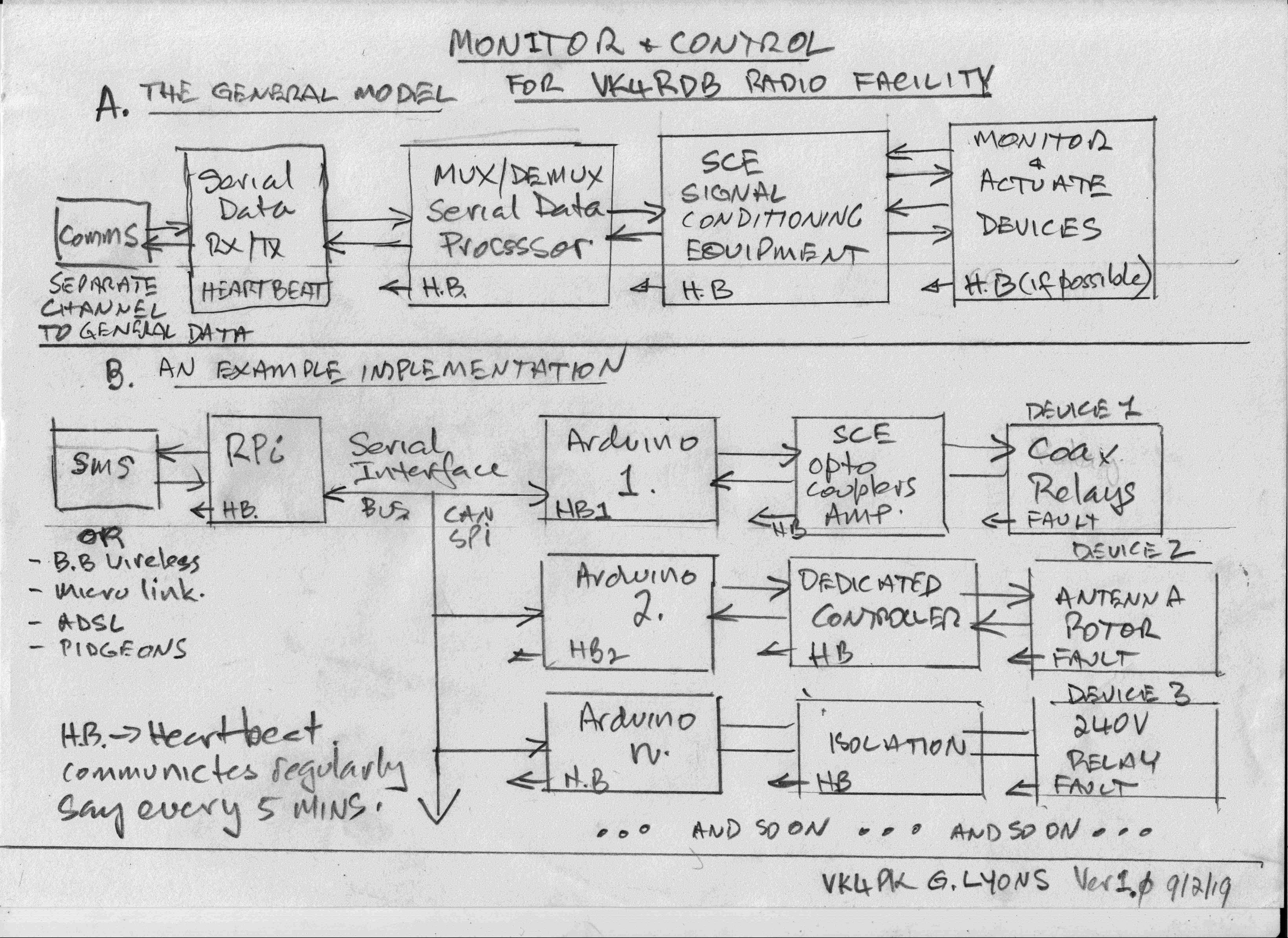
[Top][Home]
Glenn Lyons VK4PK
glenn@LyonsComputer.com.au
Ver:gnl20190202 - pre published v0.9