TX Adjustment:
For TX the best way is to use a spectrum analyzer to observe the TX RF directly.
If a spectrum analyzer is not available then an SRD configured as a
spectrum analyzer or a radio with a spectrum screen that can operate in the 70cm
band, such as an IC705 can be used.
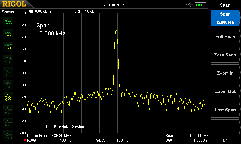
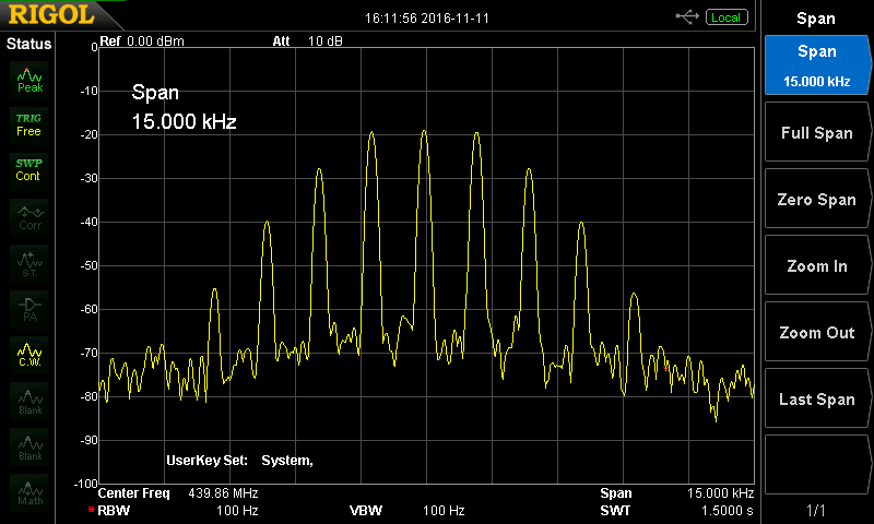
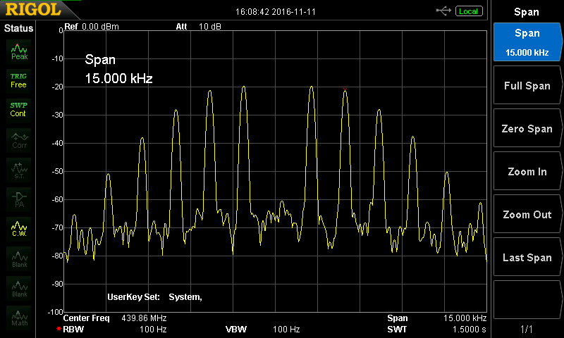
The MMDVCal program provides a 1.2kHz tone which deviation on the RF signal
should be adjusted on a level where the "Bessel zero" is clearly visible: Set
the spectrum analyzer to 1kHz RBW and tune to the RF TX frequency. Use MMDVMCal
to switch the repeater to TX and emit the DMR cal signal. While slowly turning
the TX deviation pot on the DVM board observe the sidebands of the RF signal on
the analyzer. When you've hit the right deviation level, you will notice that
the carrier in the center of the RF spectrum shows a clearly visible dip. This
is the "Bessel zero" where the deviation of both tone sidebands "zero out" the
carrier. Adjust the pot to where the dip shows maximum depth.
RX Adjustment:
For the RX use a scope to check the incoming RX signal chain from the repeater to
the DVM board. These are Test poibtas 1,2,and 3 on the Repeater Builder board.
This should be first adjusted using the clip LED on the board and then fine tuned
with the scope to create a 1,65V DC offset at TP3, which is the STM32 input.
Key you radio (on TG9 or similar...) and observe the audio on TP3 pin overlaying
the DC offset. (I've used the
rising edge of the receiver's RSSI signal for triggering the scope onto the data
bursts of my portable radio)
The RX pot on the DVM board must be adjusted so that the peak amplitude of the
audio signal does neither reach the zero line nor the 3.3V maximum or +/- 1.65v.
Keep a margin of 0.3 to 0.4V to both limits to be safe! It must be assured that
the ADC on STM32 is never overdriven by the audio signal.
With these HW adjustments you should have a suitable basic setting for operation.
For a fine tuning you may play with the TX / RX settings in the MMDVM.ini, but I
found this was not necessary when the HW tuning has been performed properly as
above.
| Command | Description |
|---|---|
| H/h | Display help |
| Q/q | Quit |
| W/w | Enable/disable modem debug messages |
| I | Toggle transmit inversion |
| i | Toggle receive inversion |
| O | Increase TX DC offset level |
| o | Decrease TX DC offset level |
| C | Increase RX DC offset level |
| c | Decrease RX DC offset level |
| P/p | Toggle PTT inversion |
| R | Increase receive level |
| r | Decrease receive level |
| T | Increase transmit level |
| t | Decrease transmit level |
| d | D-Star mode |
| D | Set DMR Deviation Mode. Generates a 1.2Khz Sinewave. Set radio for 2.75 Khz Deviation |
| L/l | DMR Low Frequency Mode (80 Hz square wave) |
| A | DMR Duplex 1031 Hz Test Pattern (TS2 CC1 ID1 TG9) |
| M/m | DMR Simplex 1031 Hz Test Pattern (CC1 ID1 TG9) |
| a | P25 1011 Hz Test Pattern (NAC293 ID1 TG1) |
| N | NXDN 1031 Hz Test Pattern (RAN1 ID1 TG1) |
| K/k | BER Test Mode (FEC) for D-Star |
| b | BER Test Mode (FEC) for DMR Simplex (CC1) |
| B | BER Test Mode (1031 Hz Test Pattern) for DMR Simplex (CC1 ID1 TG9) |
| J | BER Test Mode (FEC) for YSF |
| j | BER Test Mode (FEC) for P25 |
| n | BER Test Mode (FEC) for NXDN |
| g | POCSAG 600Hz Test Pattern |
| S/s | RSSI Mode |
| V/v | Display version of MMDVMCal |
| <space> | Toggle transmit |
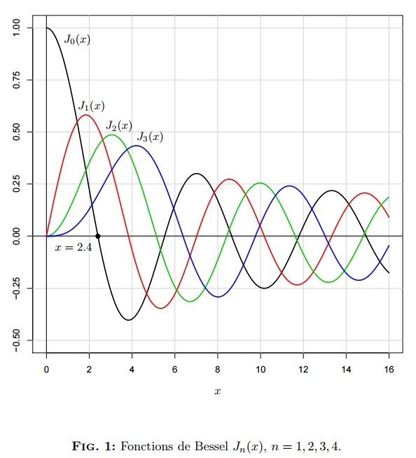
In DMR, the frequency modulation deviation must be 2.75 kHz ans 3.3 volts
peak to peak. MMDVMCal generates a signal of 1200 Hz.
The Bessel J0 appears null when the modulation index (x) is equal to 2.4.
Whe the line J0 disappears, the operating point is set to deviation of 2.88 kHz
(index = 2880/1200 = 2.4). We then reduce the TX Level (in mmdvm.ini file) by 5%
to set the required deviation.
For example, if we have a TXLevel of 85% in MMDVMCal, we will set it in mmdvm.ini
to (85*0.95 =) 81%
https://github.com/N4IRS/MMDVM-Install/wiki/RSSI