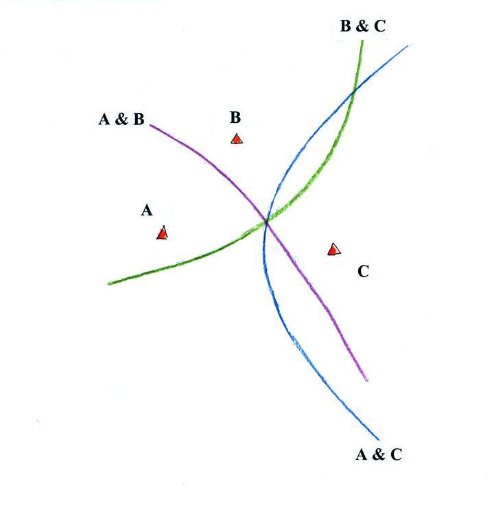
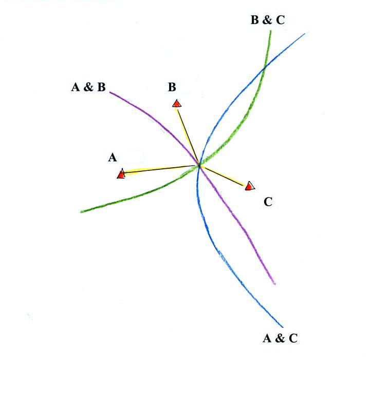
We will consider briefly the TOA technique assuming that all three stations
have either precisely synchronised clocks or accurate absolute timing (GPS timing).
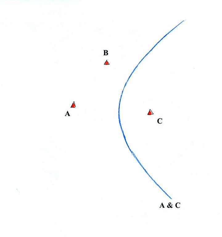
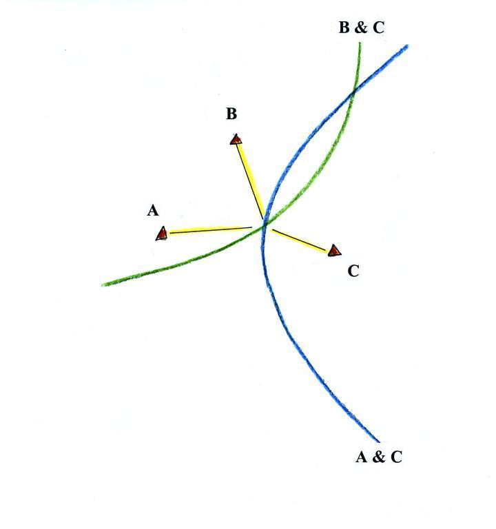
at Stations A and C from lightning striking anywhere on the blue curve (a hyperbola).
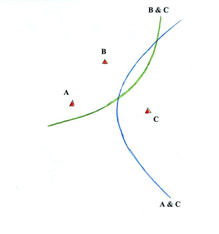
be drawn. The two curves intersect at two points.
The RF Spectrum of Lightning
NASA Technical Memorandum 87788 Review of Measurements of the RF Spectrum of Radiation from LightningThe Math Behind TOA Calculations
This reference covers, in detail some of the math involved in calculating the position on the earth's surface using the Time of Arrival method. [KS01] W.J. Koshak and R.J. Solakiewicz. TOA Lightning Location Retrieval on Spherical and Oblate Spheroidal Earth Geometries.pdf
[Top][Home]
2.0 Blitzortung
Introduction
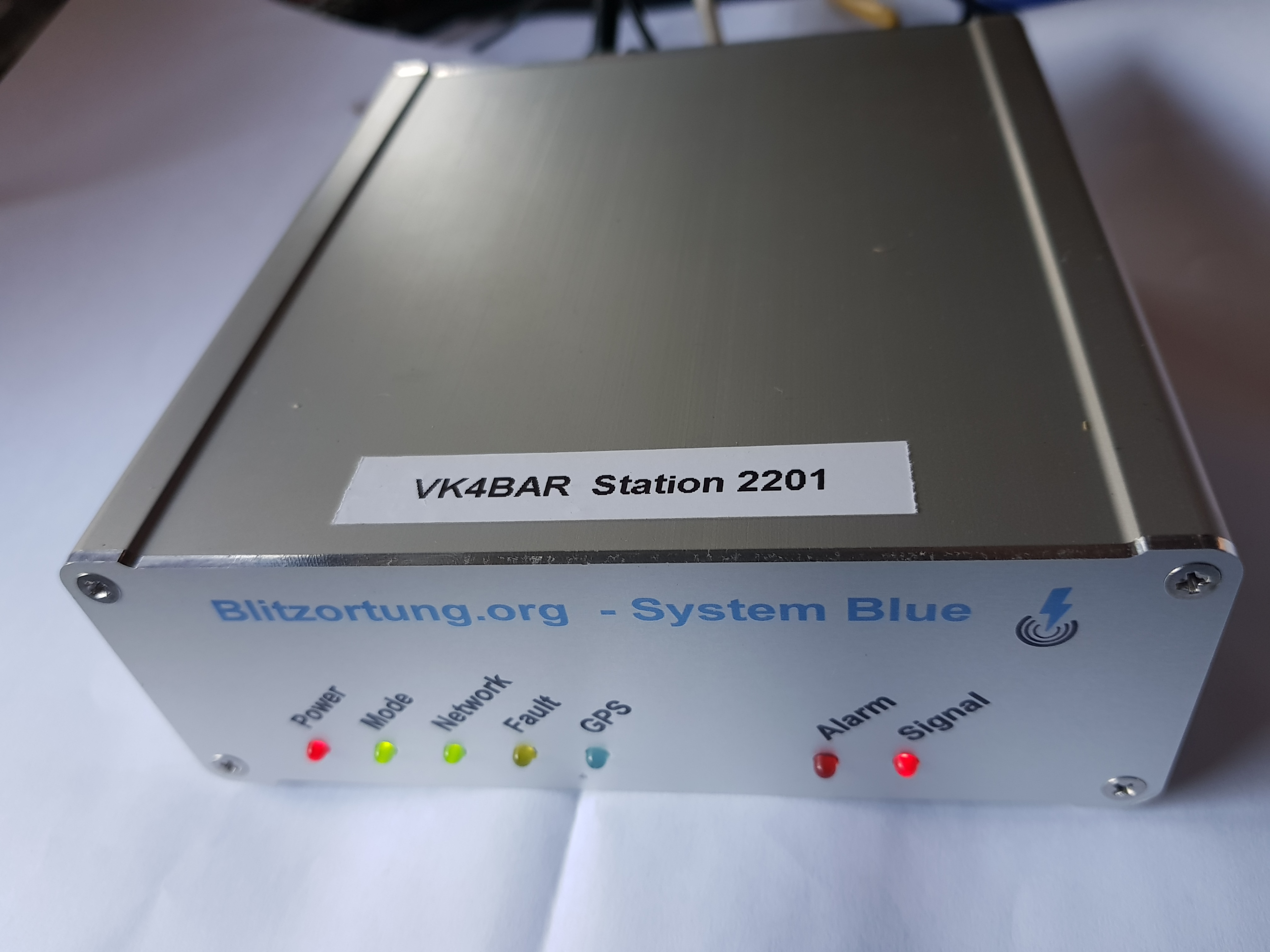
The Blitzortung comes with a unique station number and serial number.
The Bayside District Amateur Radio Society's Station Number is: 2201 and
can be accessed with this URL:
http://www.lightningmaps.org/station/2201
the Device-ID or Processor Serial Number is: 3400-4B00-1651-3631-3136-3335
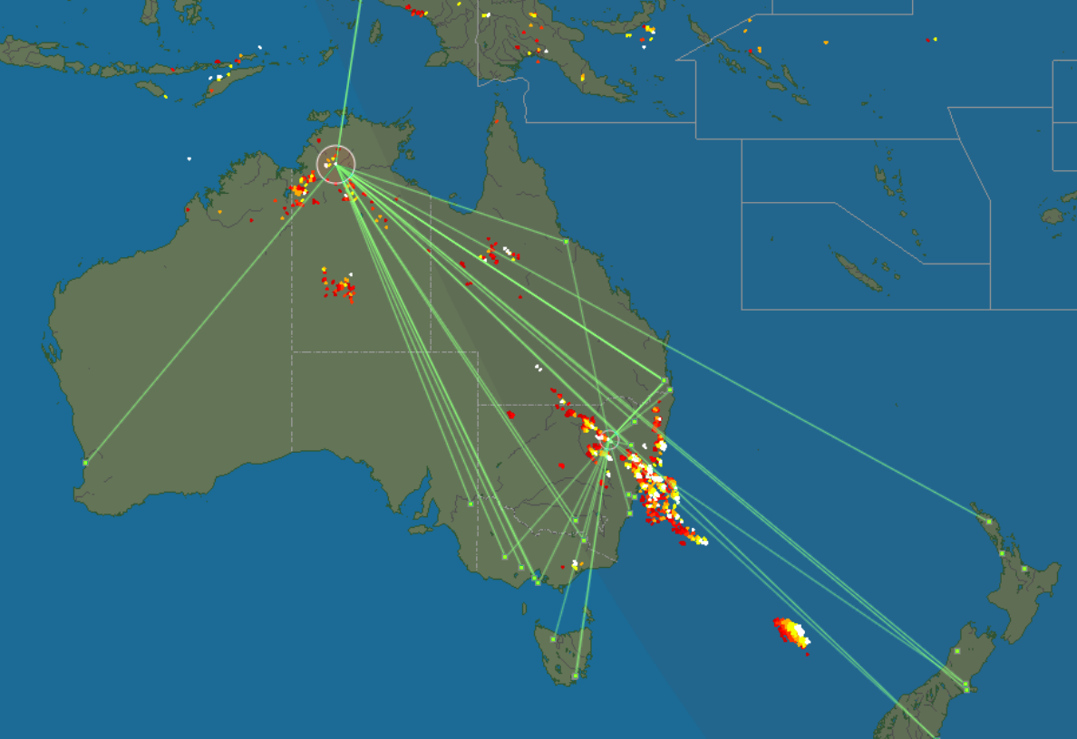
Blitzortung is a network for the detection of lightning and thunderstorms in real time.
For an introductary description of the kit construction and system administration consult the "Cover Your Area" pages at:
http://en.blitzortung.org/cover_your_area.php
The Main Login and Lightning Maps page is:
Blitzortung Login Page and Maps for Worldwide,
and the local region page is:
Blitzortung Login Page and Maps for Oceania
The data pages are available at:
Strike data for All Stations,
and site specific data page is:
Strike data for the BDARS Site No 2201
Smart Phone Apps
Apps are available for both the Andriod and iphones. Follow these links to install the appropriate App on your mobile phone.Android App: https://play.google.com/store/apps/details?id=org.blitzortung.android.app&rdid=org.blitzortung.android.app

iphone App: https://itunes.apple.com/de/app/blitzortunglive/id933558423?mt=8
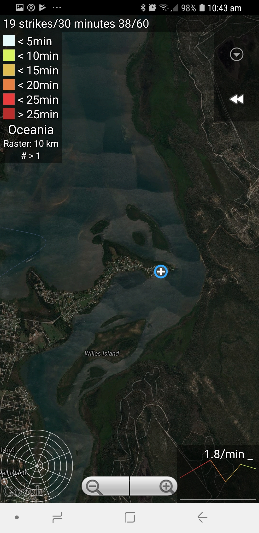
This is the app running on my Samsung and it shows the current location of the 2201 station with a cross symbol.
Construction and System Admin Documentation
Kit Construction and System Admin Documentation
The documentation for Blitzortung can only be described as shambolic.
There is a lot of details with no structure or version numbers. You simply have to dig for information.
There are several version of the same or similaid="kit-construct">Construction of the Mainboard Ver 19.4 Controller - Components, Construction, Boot, Programming and Debugging documents all with different names on different sites.
There does not appear to be any attempt at version control and many are not even published dates.
My recommendation is to read the ninety five page version of the 2014 system Red and Green manual first,
even though it is superceeded, there is a lot of information that is not covered in the sixteen page Blue Document.
HTTP://en.Blitzortung.org/Compendium/Documentations/Documentation_W_Red_PCB_10.4_PCB_12.3_PCB_13.1_PCB_14.1.PDF,
even though it applies to superseded models, as it contains more information than the fifteen page 2016 manual
HTTP://en.Blitzortung.org/Compendium/Documentations/Documentation_W_Blue_PCB_20_1.PDF.
Other Manuals and Documents worth exploring. These are copies or versions of the above manuals. Some are in PDF format.
Version 14 Documenting (pdf) - May 11, 2014
Version 20 System Blue Documentation - June 9, 2016 (pdf)
Blitzortung-Documentation-09-11-2017 (pdf)
Documentation on Google Docs - Similar to 2017 Version above (Google Docs)
http://www.blitzortung.org/Compendium/Hardware - ftp page for schematics
https://tracker.blitzortung.org/firmware/ - ftp page for firmware
This article is from 2009 and is a bit more revealing about how the system works. It shows
http://en.blitzortung.org/Compendium/Documentations/Documentation_2009-04-02_Green_PCB_4.3_PCB_3.3.pdf
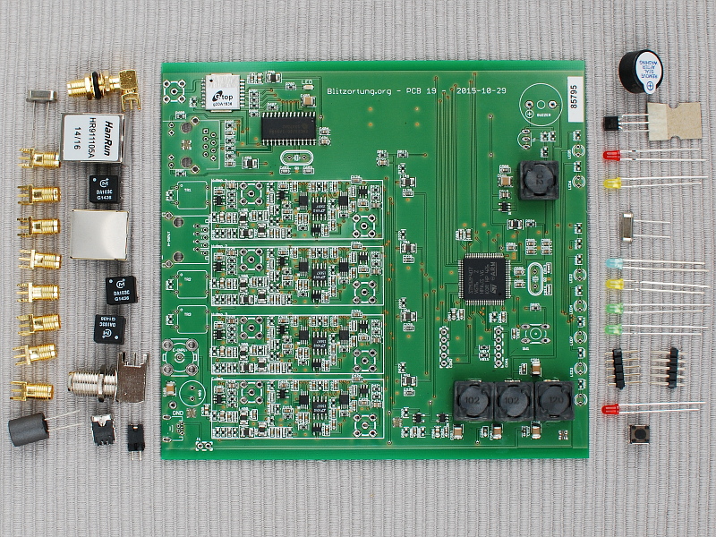
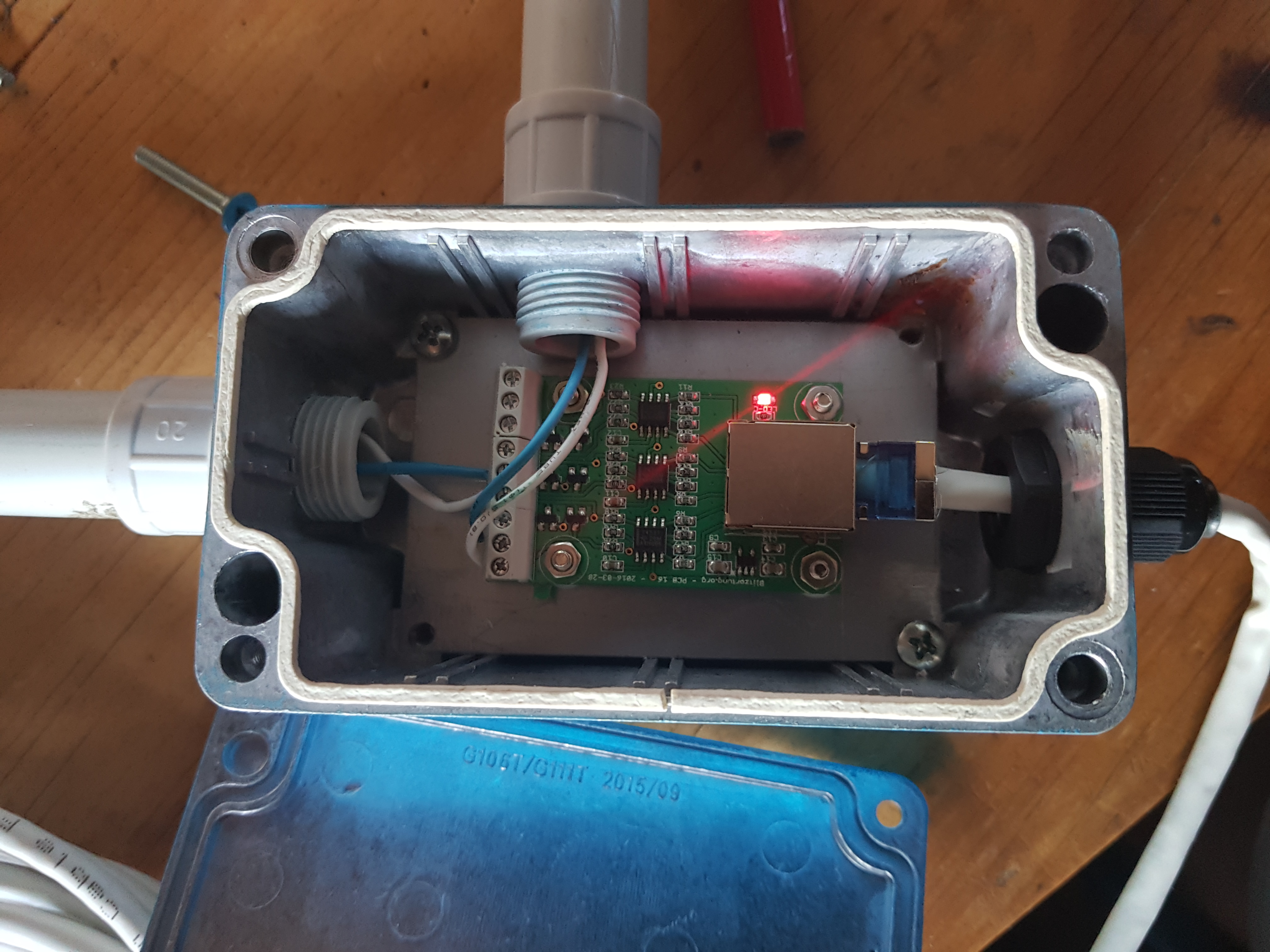
Assembly and Components
The mainboard kit arrives partly assembled with the surface mount devices mounted and the firmware installed.The kit with it's delivered components ready for assembly:
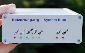
Front panel of enclosure:
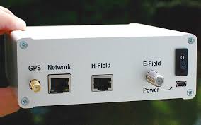
Rear panel of enclosure:
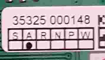
Board revision level:
David VF4ZF did an excellant job of assembling the circuit boards with little documentation.
After the build was complete a pair of 8 pin Linear Technologs Corp 15697 which are Linear Phase,
DC Accurate, Tunable, 10th Order Lowpass Filters IC's were left over.
Component: Datasheet for the 15697 Low Pass Filters (pdf)
Note about Digital Filters:
From the June 9, 2016 documentation, page 9 Section 1.6:
The complete digital filter option consists of 4 digital filter ICs (LTC1569-7)
In general, it is not necessary to install the digital filter ICs. The system also operates without
them. However, if you want to experiment, or if you have extremely strong interferences at
frequencies above 20kHz, you can try to get better signals with the digital low pass filter ICs.
Since the digital filter ICs are relatively expensive, you should test one filter IC at one channel,
preferably at the E-Field channel. If the desired effect is achieved, the other channels can be
upgraded.
Component: ENC28J60 Stand Alone Ethernet Controller with SPI Interface (pdf)
Notes about the Ethernet Controller:
Although the ARM Cortex M4 based STM32F4 micro-controllers already have an internal Ethernet
controller, they do not include an Ethernet Physical Layer Transceiver (PHY). For experimental reasons,
we additionally have placed the Ethernet controller ENC28J60 on the board of Controller 10.x.
The ENC28J60 is a very widely used "all-in-one" ethernet controller, but it can only handle 10Mbit/s
ethernet connections. With around 150mA current drawn, it has a relatively high power consumption.
The ENC28J60 is connected to the processor via SPI. In a forthcoming version, we intend to remove
the ENC28J60 and to replace it by an Ethernet Physical Layer Transceiver on the controller board.
Then we will use the internal Ethernet controller of the processor, which uses DMA and can also
handle 100MBit/s connections.
Notes: Component: GPS - GlobalTop Technology Inc - Gmm-g3 - GNSS Module
Component: 2259213-Transformers for Digital Audio Data Transmission
Debugging and Loading the Correct Firmware
Okay, are we are good to go? No! Disappointment once again. No matter what we did, we could get no more than the power LED on. Determined not to give up we conected up the network port to the routed. DHCP should give us an IP address so we searched the address range with "nmap" but no address was found. We checked the router to see if it had allocated some strange address, but no luck there as well. The Network port's green and yellow LED lights were on and flashing, maybe there was some data we could read. Next, Bob called for an extra network card, and once found proceeded to rip apart my workstation. In went the network card, and in no time Bob had tcpdump running against the interface connected to the Blitzortung. Disappointment once again. Plenty of packets were been send to the Blitzortung, which accounted for the flashing data LED on the network port, but not one packet out.
The next idea in our quest to succeed was to use the USB port, so we disconnected the USB cable from the power pack and connected it to the computer's USB port. The Blitzortung came back to life, with the power red LED on, but there was no "ding-dong" sound from the computer to indicate it had found a new device. An inspection of the loaded devices confirmed that the USB port was also inactive! More disappointment.
We decided to call it a day.
Now I was on my own with Bob and Pauls support by email and Hangouts. After reading the various manuals for the umteenth time,I decided to hook up the five pin serial port on the Blitzortung via a PL2303 serial to USB interface. What were the pinouts and what wee the voltage levels? I read in one article that Blitzortun will not release the schematics, however, after more searching I struck gold. An FTP site with all the schematics. Here is the Schematic Circuit Diagram for the Society's 19.4 mainboard. I now had the pinouts with confidence. I hooked it up, ran "minicom" and conneced to the port. It is a wounderfull feeling to see data spewing forth each time I hit the reset button. It realy is alive! I have not destroyed the board! Now, after days of reading and testing, I now had something to to go on.
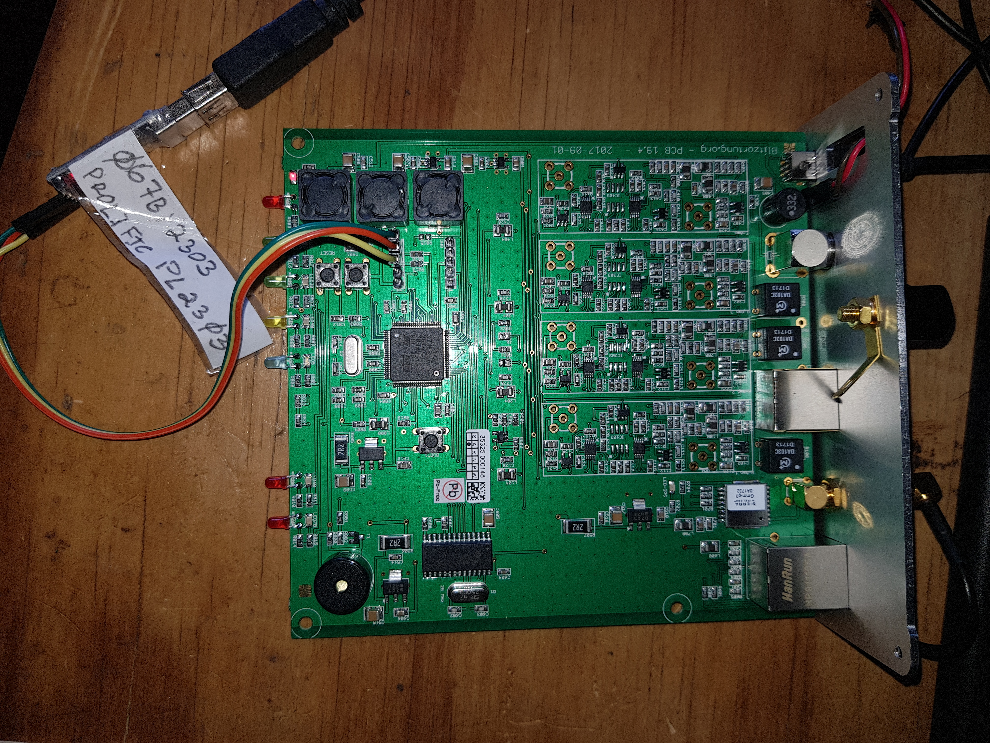
During this time I was receiving generous support and encouragement from Bob VK4YA and Paul VK4PLY. I sent them a copy of the ascii dump from the serial port. This is copy:
2000-01-01 00:00:00      0 |
2000-01-01 00:00:00      0 | === Init Timers ===
2000-01-01 00:00:00      0 | Init: Milliseconds timer
2000-01-01 00:00:00      0 | Calibrating SYSTICK delay timer... DONE! Deviation was 396.00%
2000-01-01 00:00:00      0 |
2000-01-01 00:00:00      0 | === Reading Configuration ===
2000-01-01 00:00:00      0 | Reading version information...
2000-01-01 00:00:00      0 | Flash read from 0x080fb000 to 0x080fb008 ...
2000-01-01 00:00:00      0 | Reading Blitzortung settings...
2000-01-01 00:00:00      0 | Flash read from 0x080fb028 to 0x080fb070 ...
2000-01-01 00:00:00      0 | Reading GPS settings...
2000-01-01 00:00:00      0 | Flash read from 0x080fb228 to 0x080fb234 ...
2000-01-01 00:00:00      0 | Reading amplifier settings...
2000-01-01 00:00:00      0 | Flash read from 0x080fb428 to 0x080fb4e8 ...
2000-01-01 00:00:00      0 | Reading network settings...
2000-01-01 00:00:00      0 | Flash read from 0x080fbc28 to 0x080fbc84 ...
2000-01-01 00:00:00      0 | Reading user interface settings...
2000-01-01 00:00:00      0 | Flash read from 0x080fbe28 to 0x080fbe44 ...
2000-01-01 00:00:00      0 | Reading System settings...
2000-01-01 00:00:00      0 | Flash read from 0x080fc028 to 0x080fc29c ...
2000-01-01 00:00:00      0 | Reading ADC settings...
2000-01-01 00:00:00      0 | Flash read from 0x080fc428 to 0x080fc45c ...
2000-01-01 00:00:00      0 | Settings Version is wrong, reset to zero...
2000-01-01 00:00:00      0 | Settings version 0 from flash differs from version 9 in firmware
2000-01-01 00:00:00      0 |
2000-01-01 00:00:00      0 |
2000-01-01 00:00:00      0 | ================ Blitzortung STM32F4 Controller Board ================
2000-01-01 00:00:00      0 | Firmware Rev. 8.3 RED / Nov 14 2017 23:01:37 (Git 8.3-0-g9bad3f2)
2000-01-01 00:00:00      0 | Hardware Rev. 10.4 (Id 2)
2000-01-01 00:00:00      0 | PCB Config Id 0
2000-01-01 00:00:00      0 | Flash size 1024kB
2000-01-01 00:00:00      0 | Reset condition: BOR=1 PIN=1 POR=1 SOFT=0 IWD=0 WWD=0 LPW=0
2000-01-01 00:00:00      0 | Reset states: 00000000 00000000 00000000
2000-01-01 00:00:00      0 |               00000000 00000000 00000000 00000000
2000-01-01 00:00:00      0 | HCLK: 168MHz
2000-01-01 00:00:00      0 | PCLK1 (APB1): 42MHz
2000-01-01 00:00:00      0 | PCLK2 (APB2): 84MHz
2000-01-01 00:00:00      0 | SYSCLK: 168MHz
2000-01-01 00:00:00      0 | Device-ID: 3400-4B00-1651-3631-3136-3335
2000-01-01 00:00:00      0 | Heap:  0x200120f4 - 0x2001c778
2000-01-01 00:00:00      0 | Stack: 0x2001c778 - 0x2001e778
2000-01-01 00:00:00      0 | ======================================================================
2000-01-01 00:00:00      0 |
2000-01-01 00:00:00      0 |
2000-01-01 00:00:00      0 | === Init SED1520 ===
2000-01-01 00:00:00      0 | Brightness: 70%
2000-01-01 00:00:00      0 | Contrast: 60%
2000-01-01 00:00:00      0 | Init LCD Contrast Timer
2000-01-01 00:00:00      0 | Init: Display Backlight Timer...
2000-01-01 00:00:00      0 |
2000-01-01 00:00:00      0 | DEBUG MODE ENABLED!
2000-01-01 00:00:00      0 | SYSTEM WATCHDOG NOT ENABLED!
2000-01-01 00:00:00      0 | HOLD THE BUTTON TO RESET YOUR SETTINGS...
2000-01-01 00:00:00      0 | .............................................
2000-01-01 00:00:00      0 | ERASING SETTINGS...
2000-01-01 00:00:00      0 | -> Deleting...
2000-01-01 00:00:00      0 | Done.
Paul was quick to respond. The wrong Firmware had been loaded onto the board in Germany! It was "Firmware Rev. 8.3 RED" on a BLUE board!
Next, I had to figure out how to get the correct System Blue firmware on to the crippled main board. The convention method is to use Single Wire Debug (SWD) with the ST Link adapter and the associated Single Wire Debug (SWD) software utility. I immediatly ordered one from China and decided to do some more research while I waited for it's arrival. The St-Link procedure is described in Section 1.7.2 "Single Wire Debug (SWD)" of the Documentation_2016-05-04_Blue_PCB_20_1.pdf.
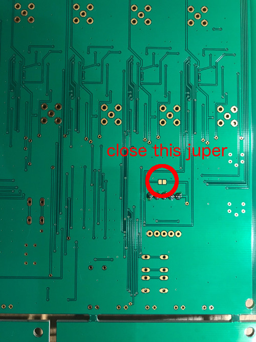
Then I read about loading the firmware via the USB port. However, I thought that is not going to work because the USB port, like the network port, is "dead". Then I discovered there is a jumper on the rear of the board that enables the USB port to be more than a power supply.
But how do I load the firmware? Well there is yet another version of the System Blue Documentation that tells you how.
It is a google docs site:
https://docs.google.com/document/d/1KzPZJW0ErInFtfTCmhNhSZTOpg6N2bgZDyIxkh_DRVs/pub#h.37876g5o2ego
Search for Section 2.4.3, "Device Firmware STMicroelectronics Extension (DfuSe)". As it instructs, I downloaded the DfuSe utility and the correct System BLUE dfu version of the latest firmware, which is, as at writing is Ver 8.4b, from
https://tracker.blitzortung.org/firmware/dfu/.
This is actually an ftp site. With the jumper closed, I connected the mainboard to the computers USB port. It was recognised immediatly.
The firmware load without a hitch. I rebooted the Blitzortung and it came to life with all LED flasting as expected.
A few minutes later the GPS handed over to the mainboard and the blue GPS LED became active. The Web Interface strang to life. Success! All system nominal! There was nothing else left to do but install the two antennas and later fine tune the paramater settings, and watch the data roll in.
The linux version of the DFU utility can be found here: http://dfu-util.sourceforge.net - FW Utility for Linux/
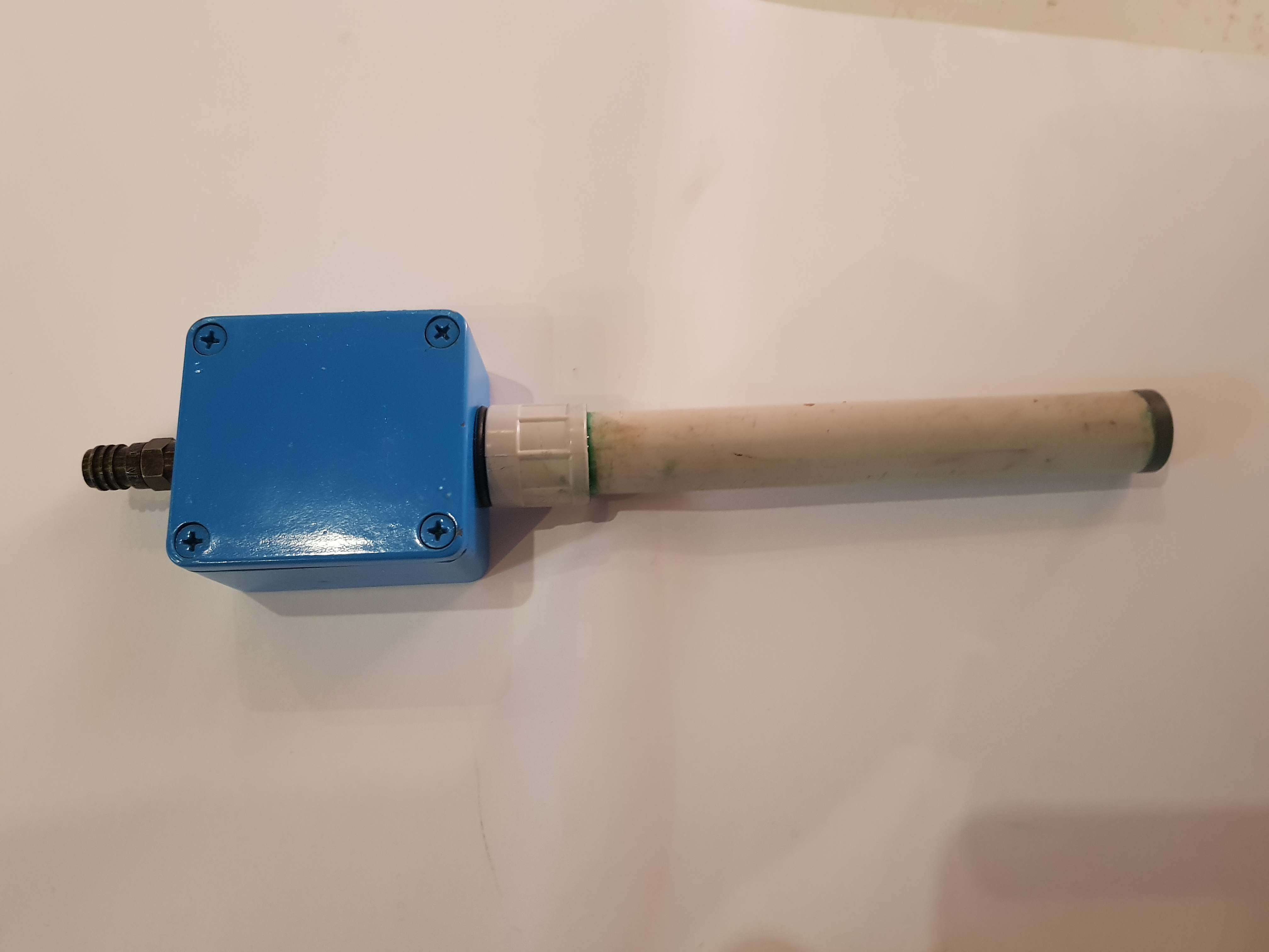
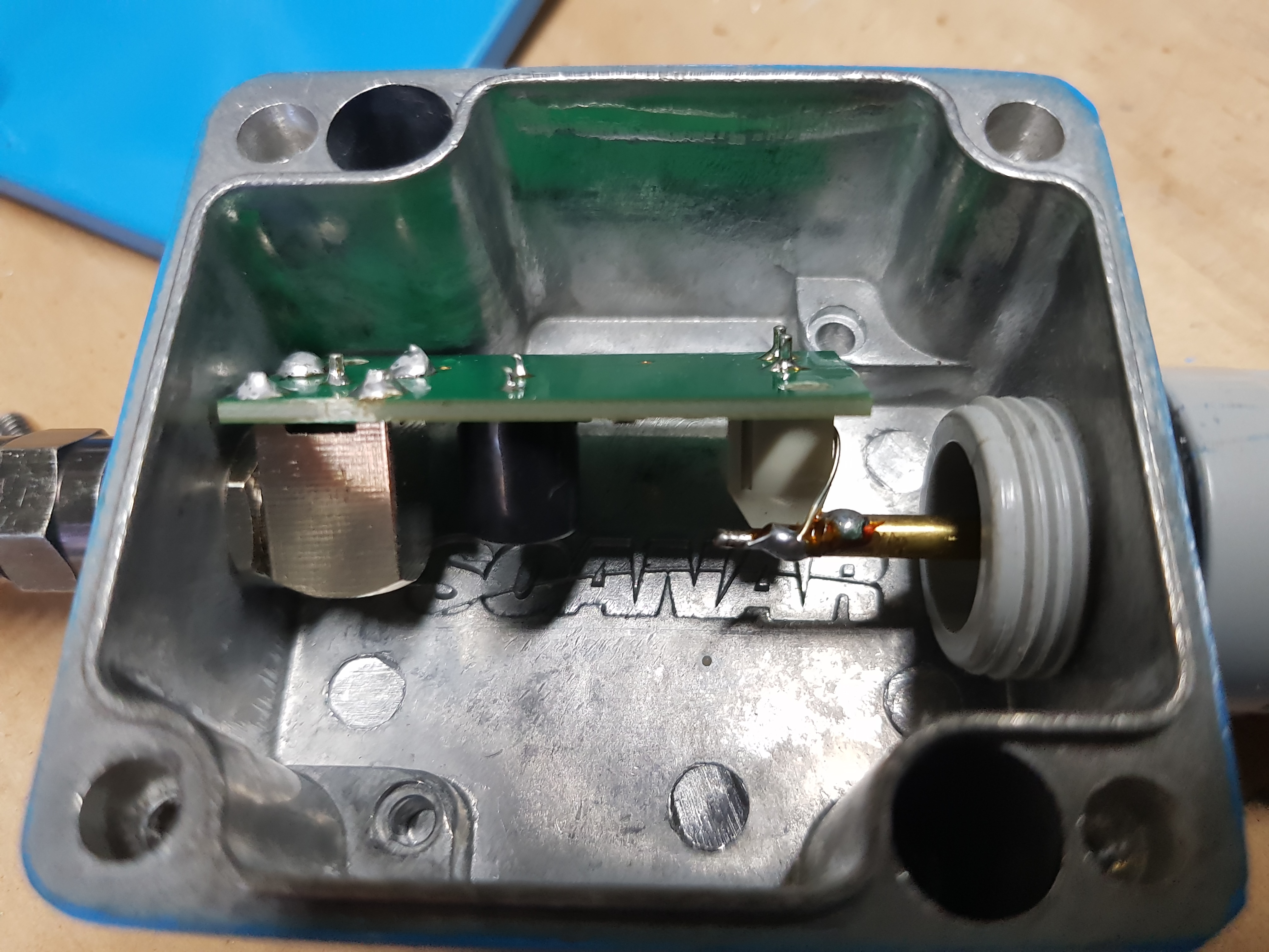
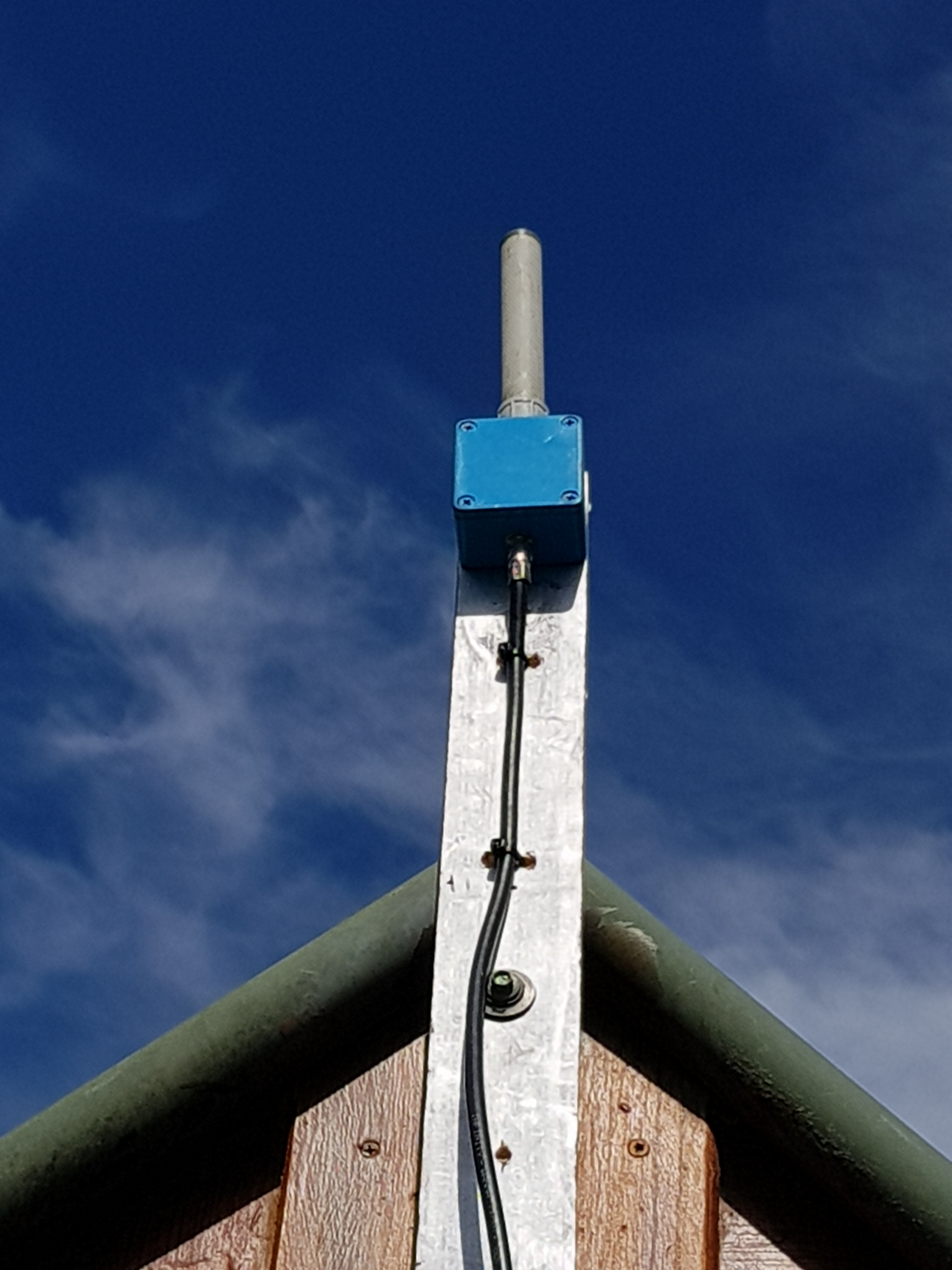
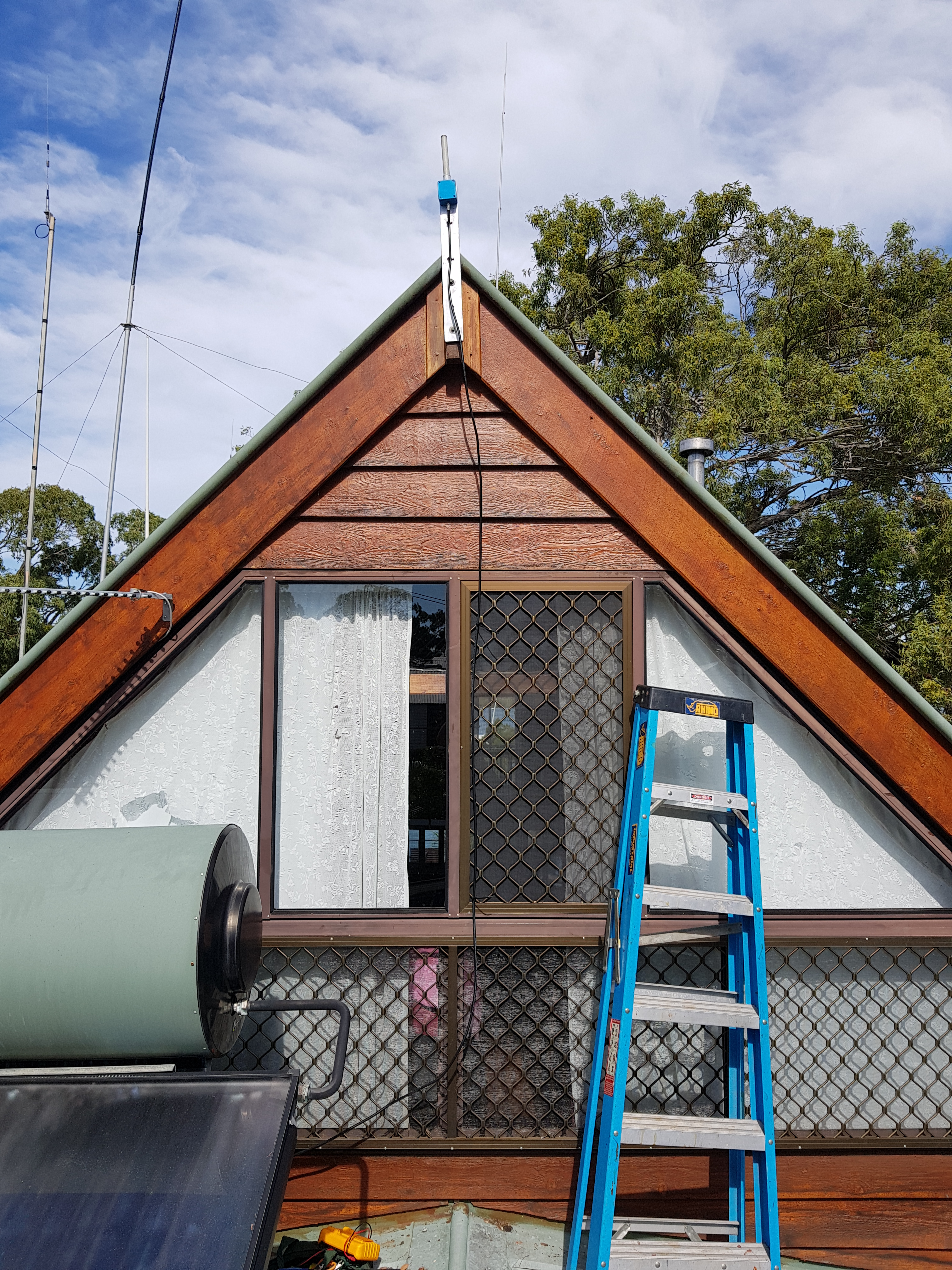
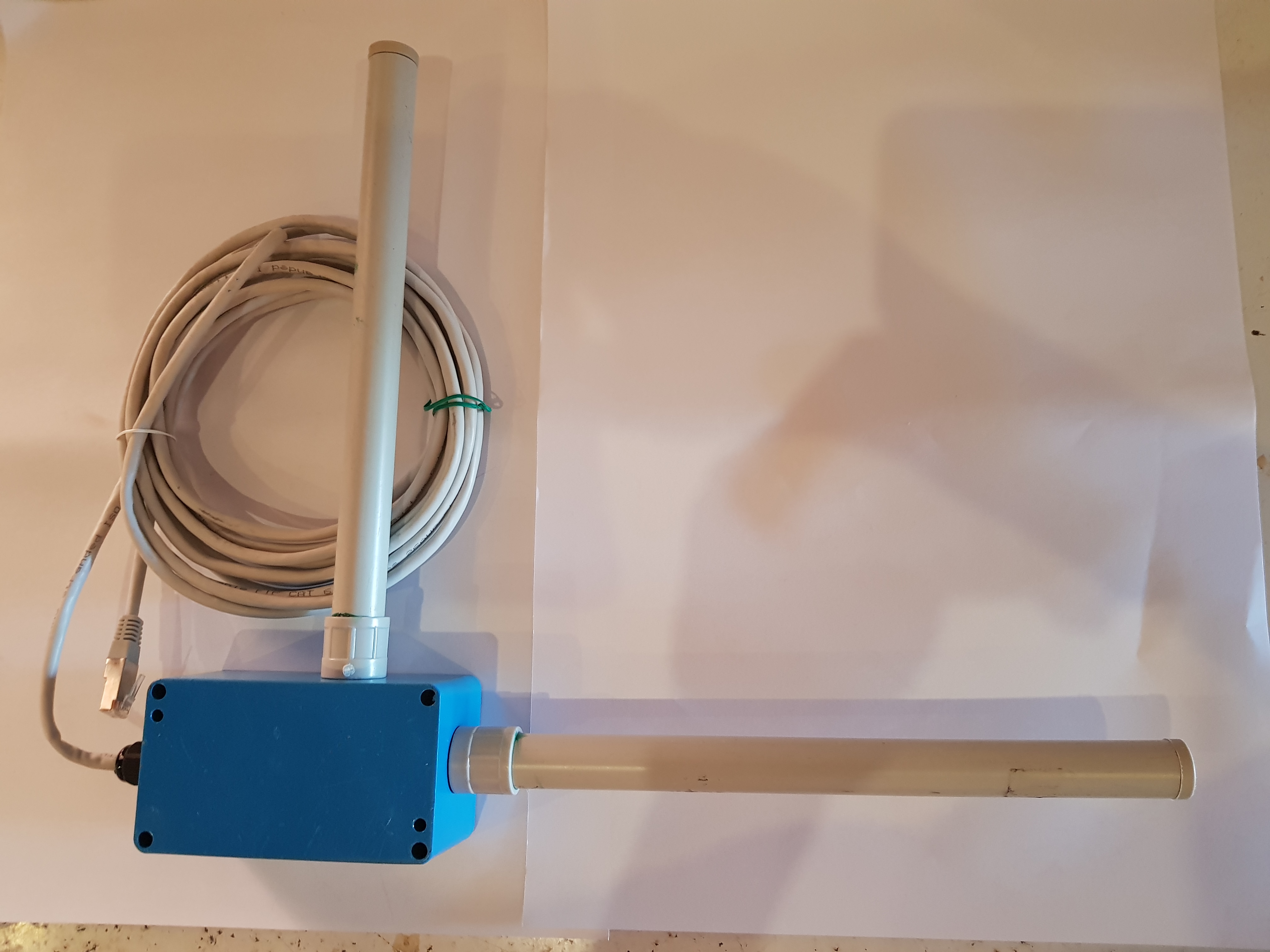
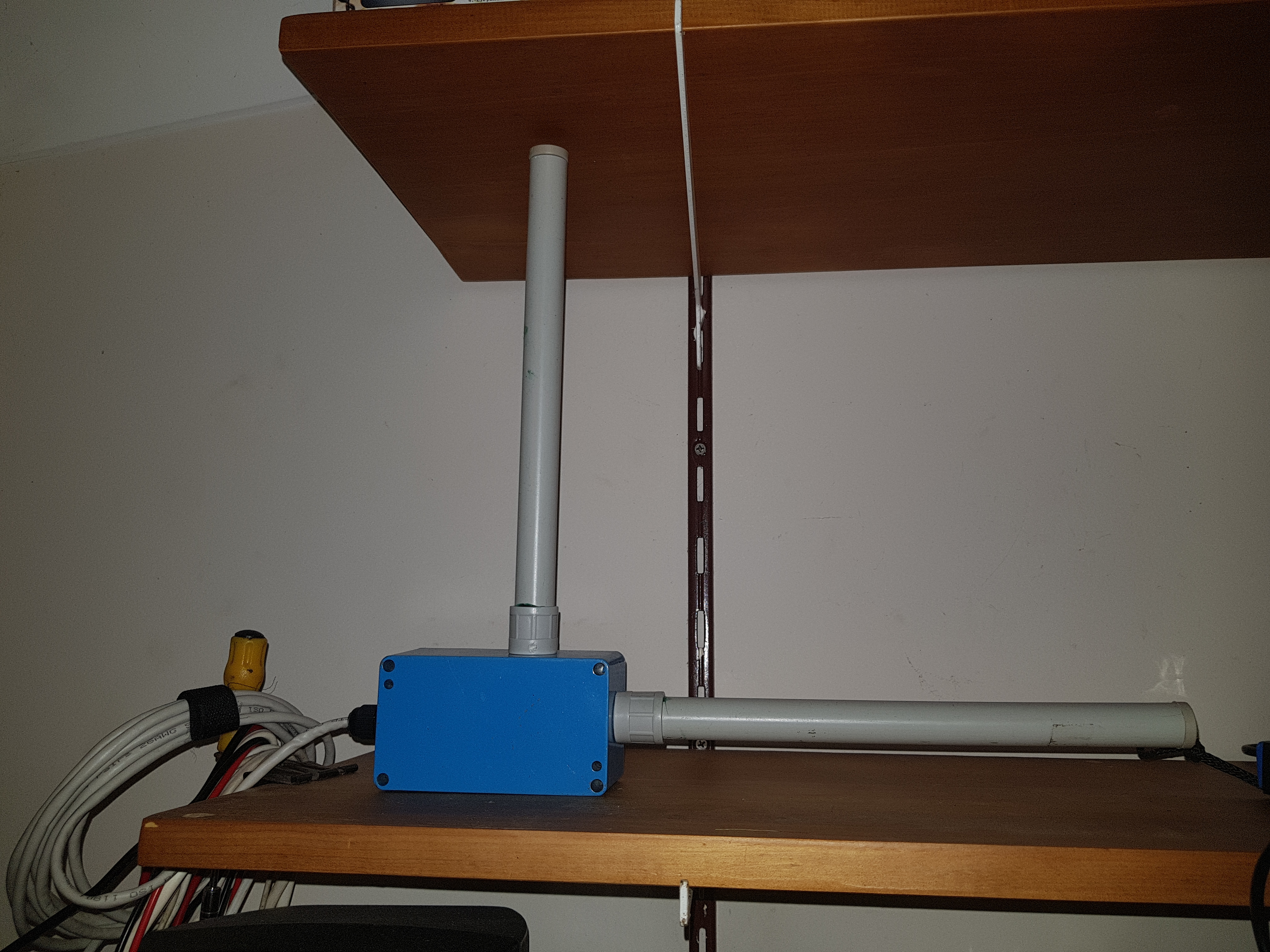
Antenna Systems
Documentation for the installation of the antennas can be found in this pdf: Documentation_2016-05-31_Antennas (pdf)The E-Antenna was installed with a 25 meter RG6 quad shielded 75 ohm feedline on the peak of the roof.
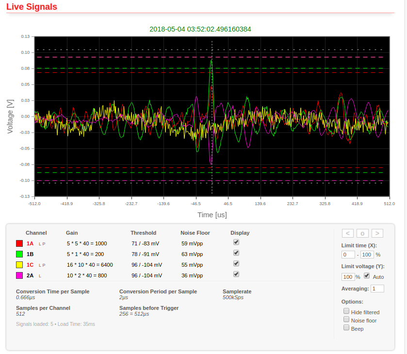
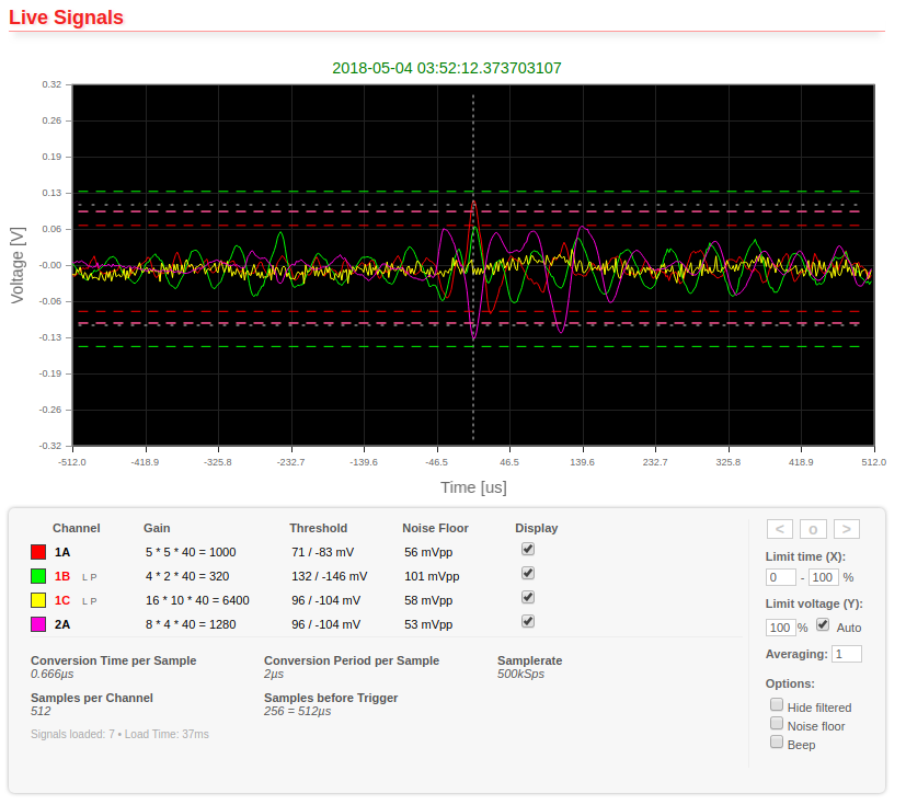
The Local Web Interface to the Controller
The Web interface is intalled in the firmware of the mainboard controller and is accessed by typing a local IP address eg "192.168.1.90" into the browser. This PDF shows the Web Interface of the Society's Blitzortung controller: The Web Interface (pdf)
Blitzortung Kit Video
https://www.youtube.com/watch?v=hpKbZC1DEp4 - System Red Kit Construction Run ...[Duration: 29:59 Min:Sec]
https://www.youtube.com/watch?v=Vjy7iZr-u_Y - System Red Blitzortung WEB Controller ...[Duration: 54:09 Min:Sec]
https://www.youtube.com/watch?v=7Jcmte5TWX4 - Fast Forward System Blue Assembly with No Audio ...[Duration: 5:00 Min:Sec]
Articles on Older Red Kit Construction
https://www.codeproject.com/Articles/809240/Lightning-Never-Strikes-Twice-Blitzortung - CodeProjecthttp://www.bismarckweather.net/Temp/Blitzortung_Build.pdf
Usefull Applications available from github
1. Blitzortung openwrt Tracker
Package building resources for the ToA Lightning Detection Tracker Program for OpenWrt. OpenWrt, https://openwrt.org/ is an open source project for embedded operating system based on Linux, primarily used on embedded devices to route network traffic. The main components are Linux, util-linux, musl, and BusyBox.
https://github.com/KiNgMaR/blitzortung_tracker_openwrt2. STLink Open
Linux based commkand line open source version of the STMicroelectronics Stlink Toolsused to load the Blitzortung firmware over the USB port.
github Archive of the Open STM32 Firmware and Debug Tool (local)
[Top][Home]
DIY Receivers
Reciever Circuits
http://www.techlib.com/electronics/lightning.htmlhttps://www.youtube.com/watch?v=-8aJDfnLakY - >DIY Receiver Video
[Top][Home]
Arduino Detectors
https://create.arduino.cc/projecthub/runtimeprojects/a-lightning-detector-for-arduino-9f679chttp://www.instructables.com/id/Arduino-Pocket-Lightning-Detector
[Top][Home]
Lightning Location by Doppler
https://hackaday.com/2018/01/23/shmoocon-delightful-doppler-direction-finding-with-software-defined-radio/"[Top][Home]
Live Lightning Detection Networks Sites
Blitzortunghttp://en.blitzortung.org/live_lightning_maps.php?map=20 - Blitzortung Login Page and Maps for Oceania
LightningMaps.org - A community project with free lightning maps and apps [Note this is based on Blitzortung]
https://www.lightningmaps.org/blitzortung/oceania/index.php?lang=en - Lightning Maps
An Australian company, Global Position and Tracking Systems Pty. Ltd. (GPATS)
http://www.gpats.com.au/australian-real-time-feed - GPATS lightning detection centre.
The CSIRO's, AUSTRALIA TELESCOPE NATIONAL FACILITY Lightning Detector
http://www.narrabri.atnf.csiro.au/mopra/lightning/ - ATNF Lightning Detector
Gorge Creek Orchards - 10 km west of Mareeba, Home of Live Weather Data
http://www.gorgecreekorchards.com.au/lightningfull.html - Gorge Creek Orchards
[Top][Home]
References to additional sites in Europe and the US:
- European lightning detection networks, reference links
- WWLN Current lightning
- ORF.at European lightning
- Euclid Current lightning, 1 hr delayed
- Siemens Partial coverage, 30 minutes delay
- MeteoTest Lightning in Switzerland
- AEMet Spain Lightning in Spain
- DMI Denmark Lightning in Denmark
- US lightning detection networks, reference links
- Accuweather Current lightning, 30 min delayed
- Vaisala Lightning last 2 hrs, 1 hr delayed
- USPLN Current lightning, 15 min delayed
- Intellicast Current lightning, 30 min delayed
- WWLN Current lightning, America
[Top][Home]
Glenn Lyons VK4PK
glenn@LyonsComputer.com.au
Ver:gnl20180506 - published v1.1