[Top][Home]
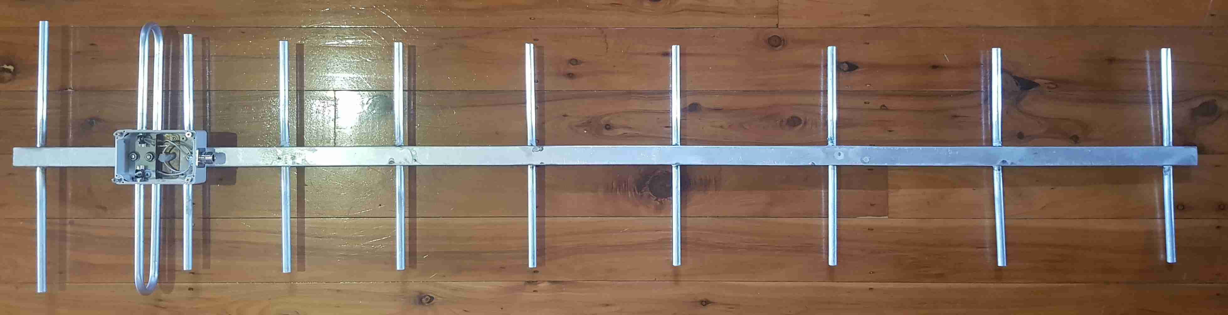
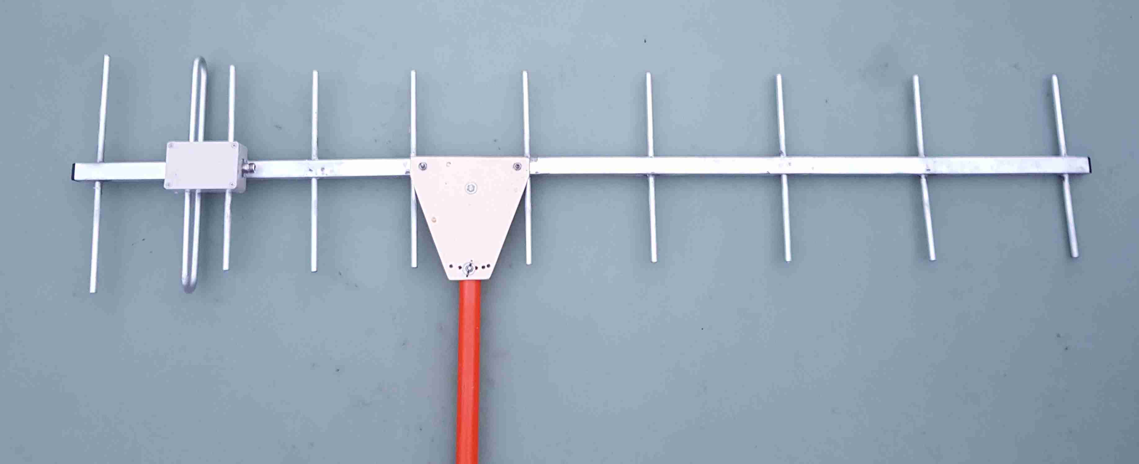
I decided to be a little conservative a build an eight element UHF
antenna for my second at building a Yagi. The first attempt to build a Yagi
antenna was a thirteen element VHF Yaga and is still not complete.
It was a little to ambitious but I will get back to it.
I looked around for similar projects and was inspired by Ralph Klimek's
70cm 11 element yagi array project.
http://users.monash.edu.au/~ralphk/70cm-yagi.html
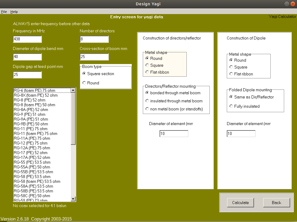
He also chose to design with the VK5DJ Yagi Calculator and has some interesting
construction suggestions.
[Top][Home]
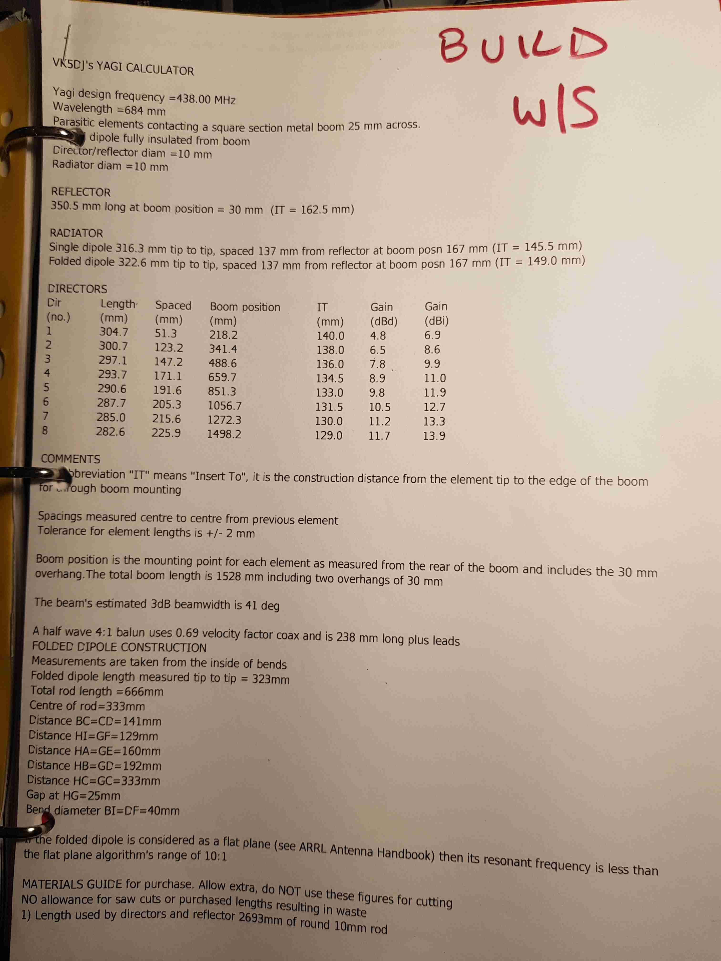
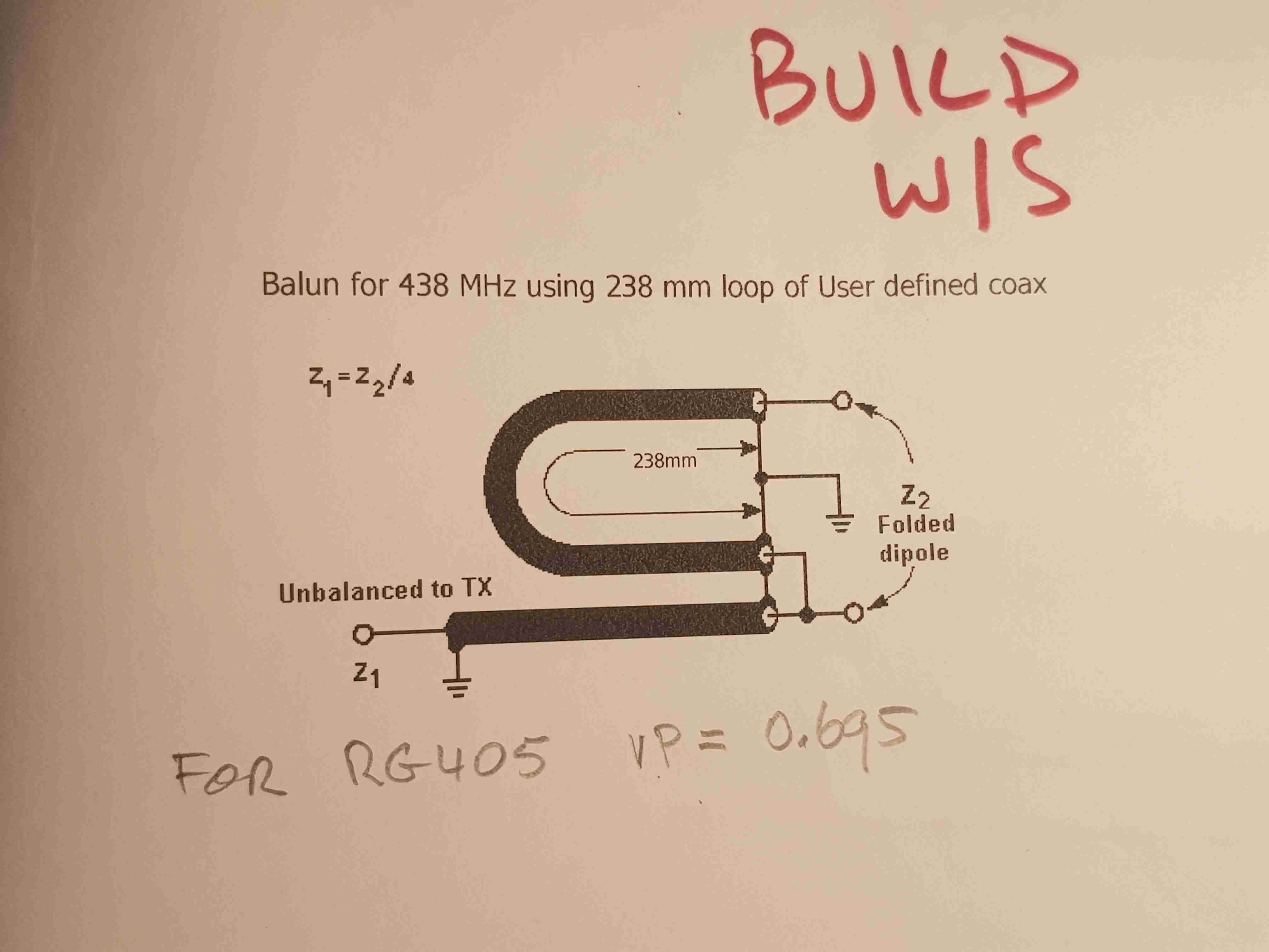
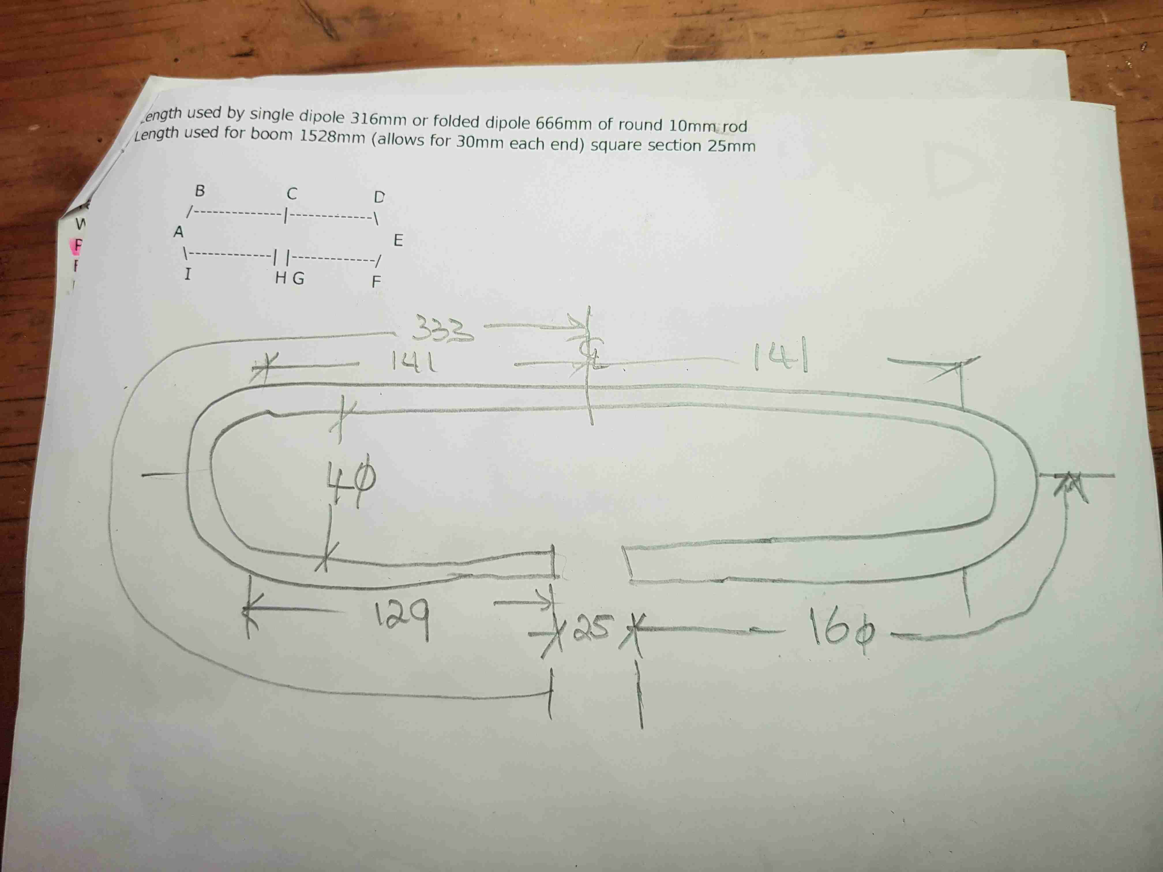
I make a printout and label the documents "BUILD W/S", and make sketches to
aide the folding of the dipole. I can then take these to the workshop for the
construction phase.
[Top][Home]
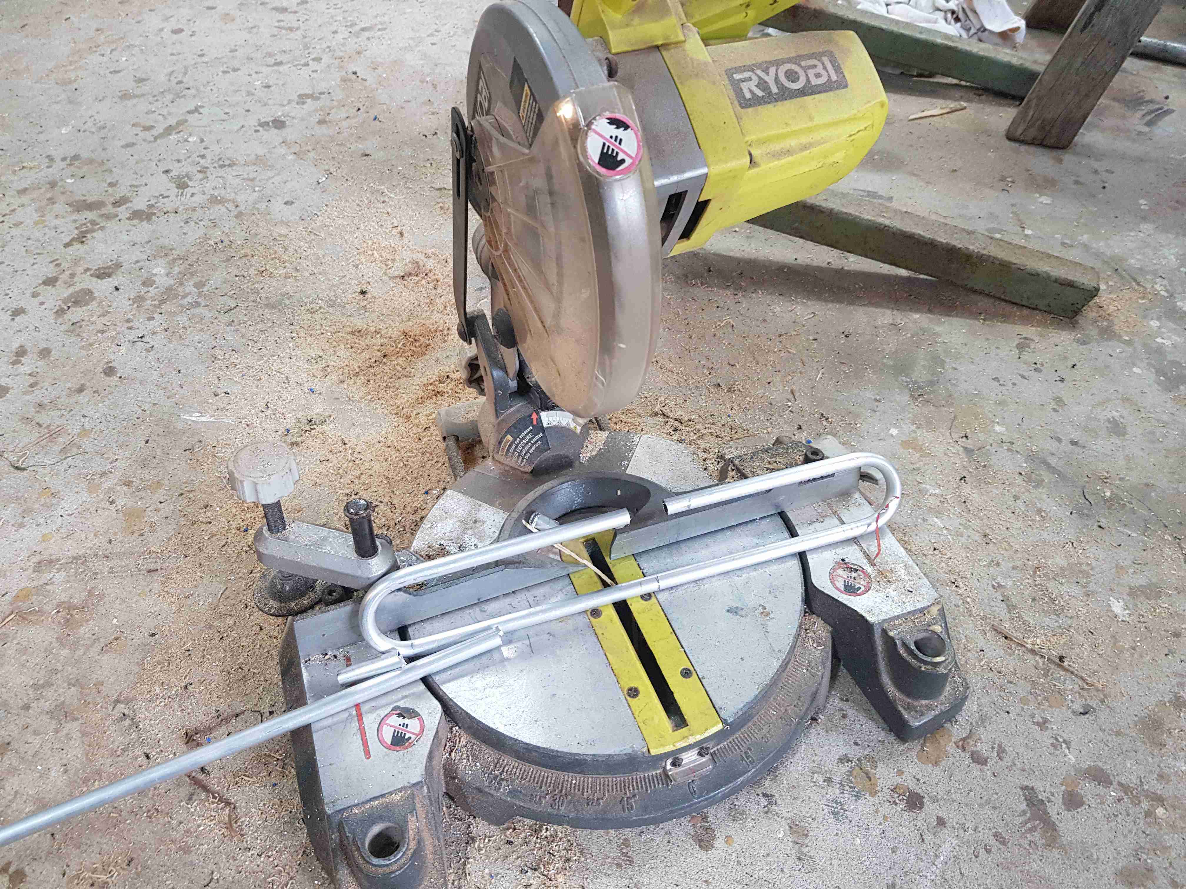
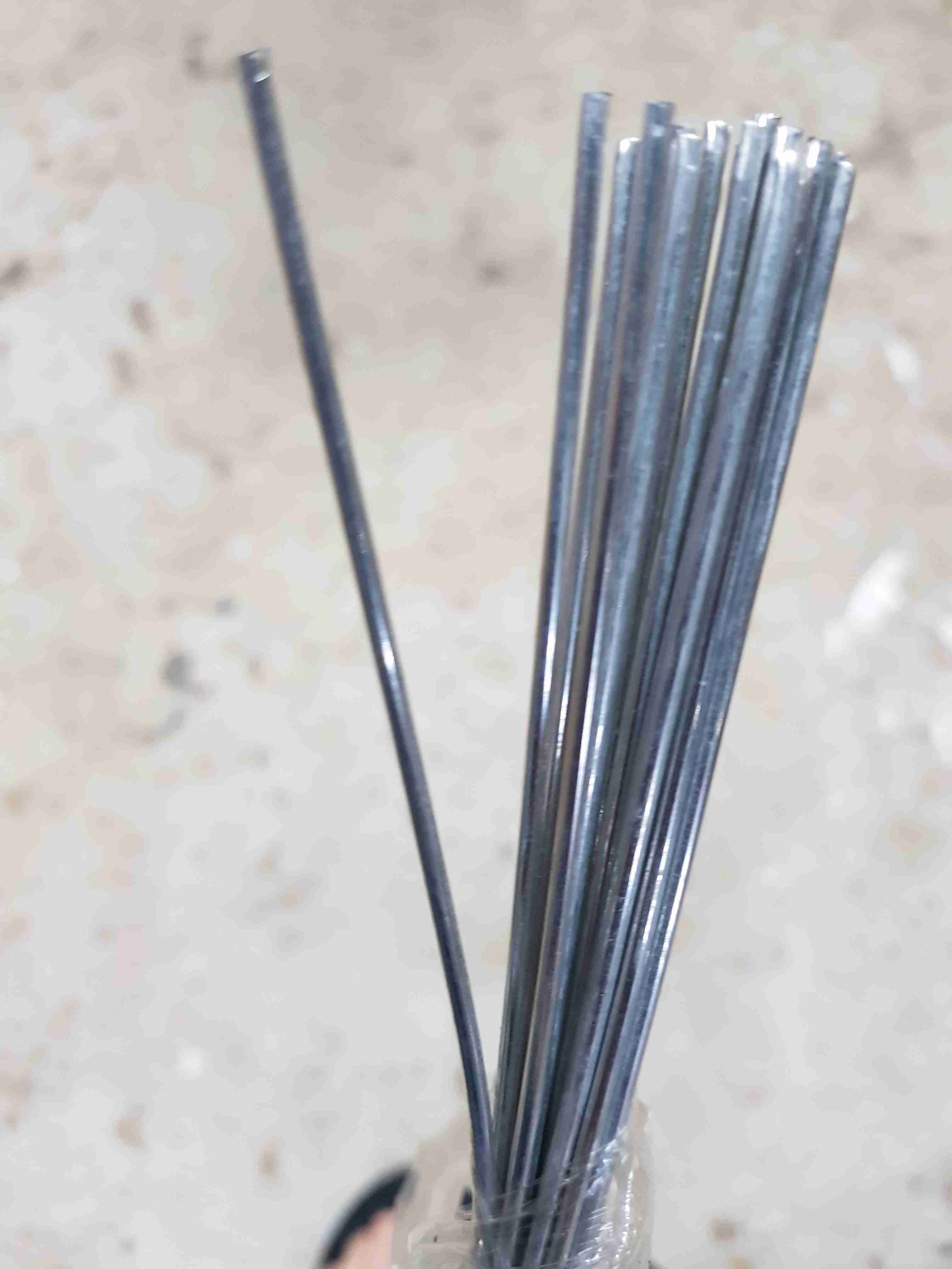
I purchased twenty 500mm long of Low Temperature Aluminum Welding Solder Rods.
They cost AU$13.86 delivered. They are like Wire Brazing rods for aluminium and
soften before the alumunium melts. You have to be careful not to overheat the
job or the antenna is lost in a puddle of molten aluminium. It was time
consuming work soldereing the elements both sides of the center beam. Next time
I will buy a canister of argon gas and try my hand at aluminium TIG welding.
You do not need any flux powder. I tried using aluminium flux powder but it did
not appear to make any difference.
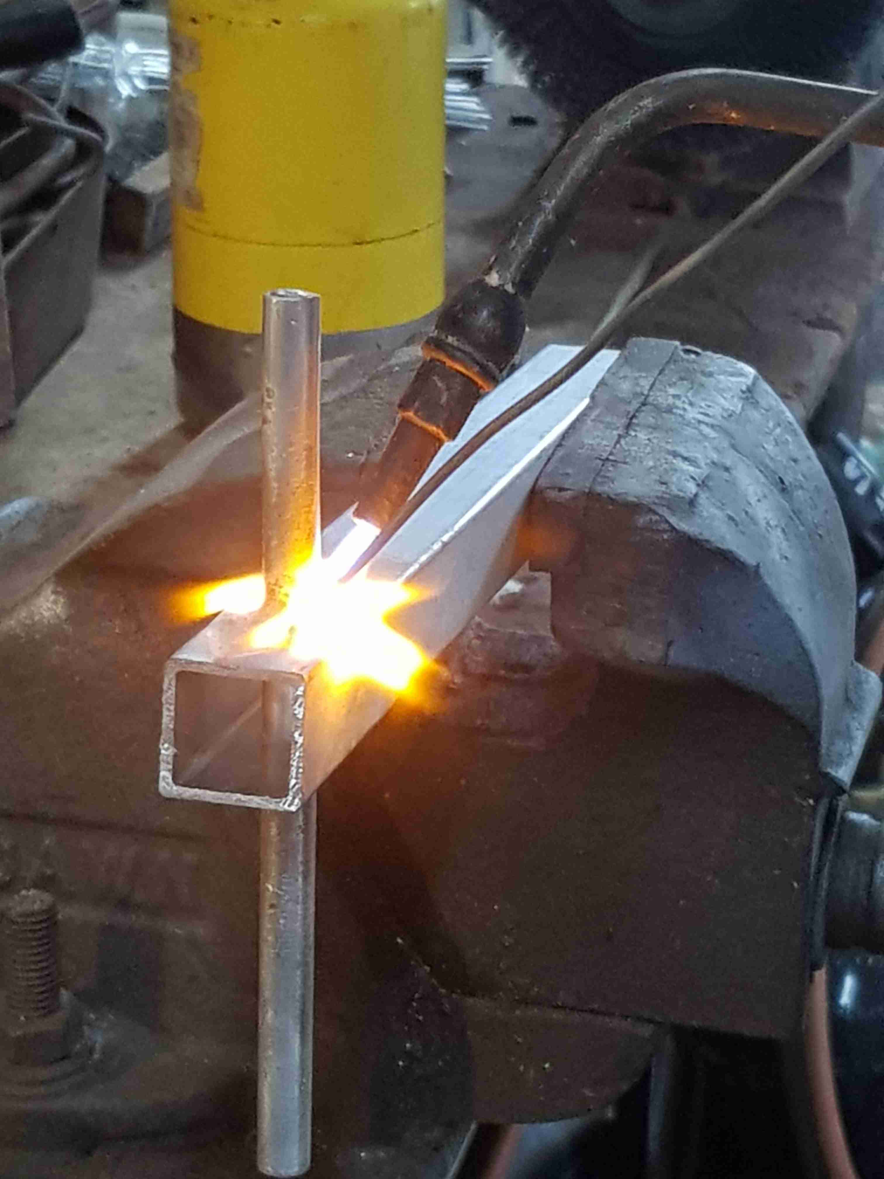
The application is similar to silver soldering. The welding area must be clean
fresh aluminium so I used sandpaper to polish the welded parts. I applied heat
evenly moving the flame over the welded parts. The temperature must rise to
360C degrees, for the copper and aluminum welding rod to melt evenly into the
joint. Do not apply the flame to the welding rod, only to the job. Remove the
torch after the weld flows.
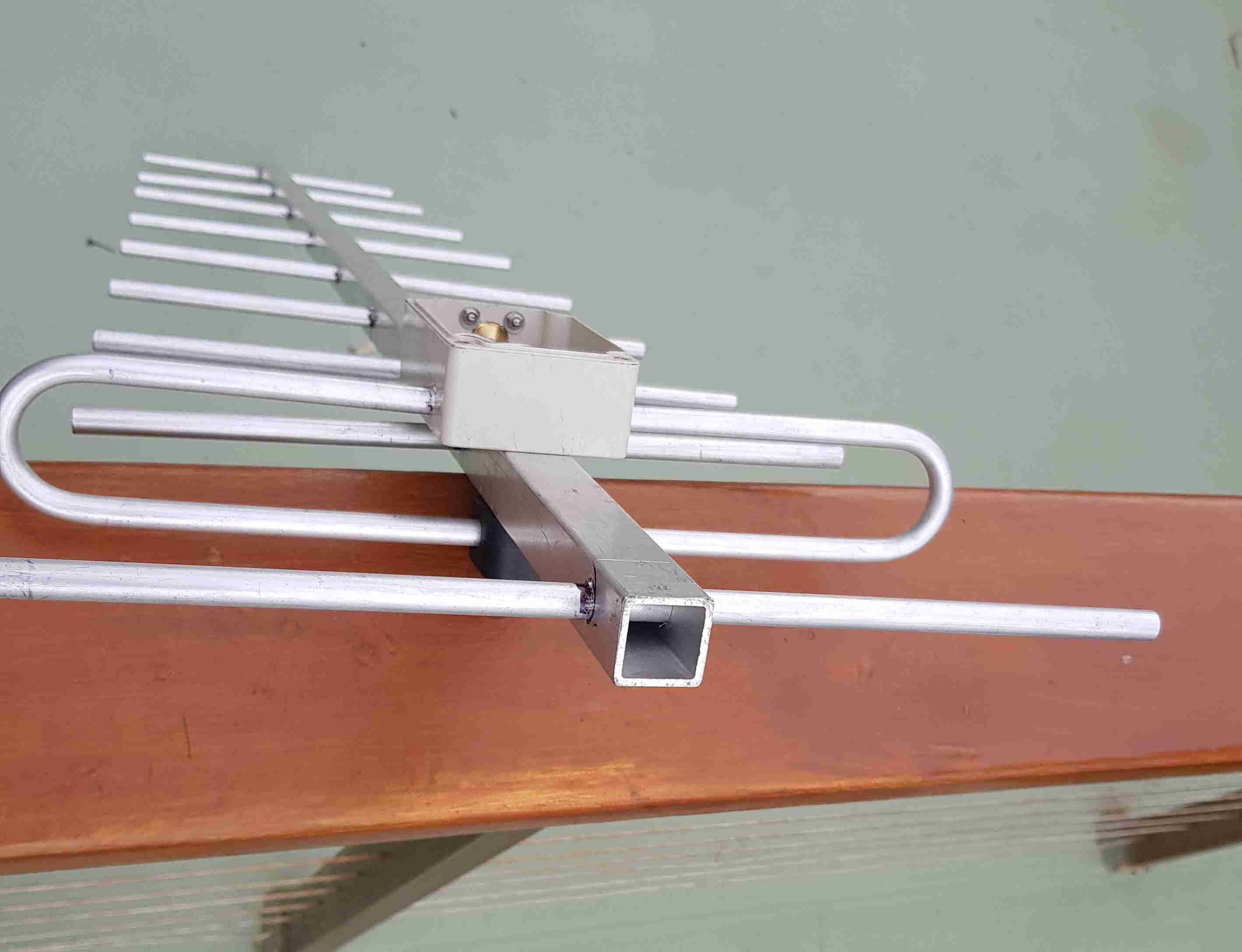
I used a small section of the 25x25 aluminium RHS section and a 10mm tube to test Soldering the aluminium and develope my technique.
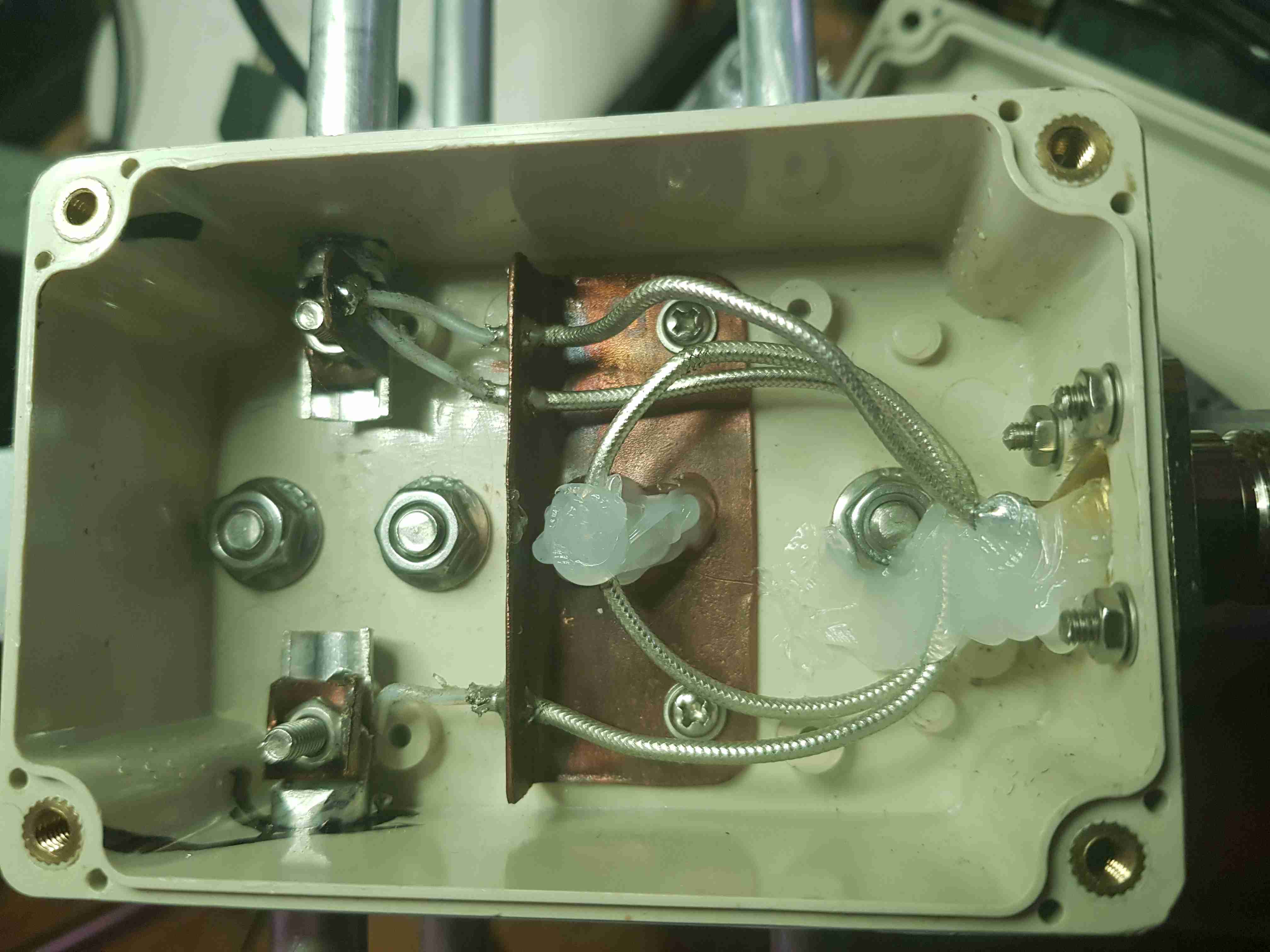
To make the copper supporting bracket that I could solder the coaxial cable's
shield to, I use a small offcut of copper water pipe and slit it lenghtways,
and hammer it flat, before bending to make the angle.
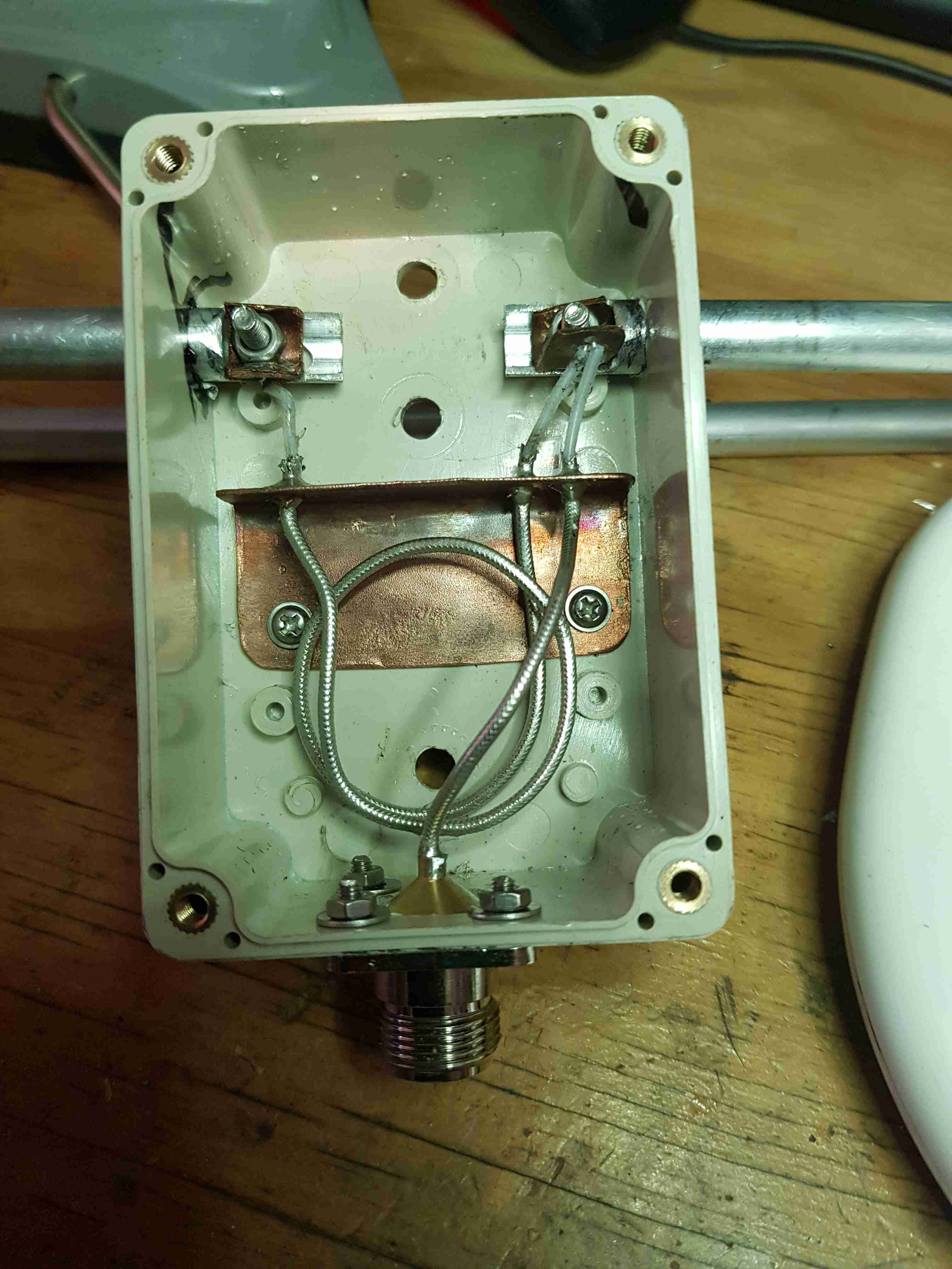
Soldering the RG405 to the copper was a little tricky. I made lugs from the
same copper pipe so I could solder directly to the the lugs and the bolt the lugs
to the ends of the aluminium dipole ensuring a good contact.
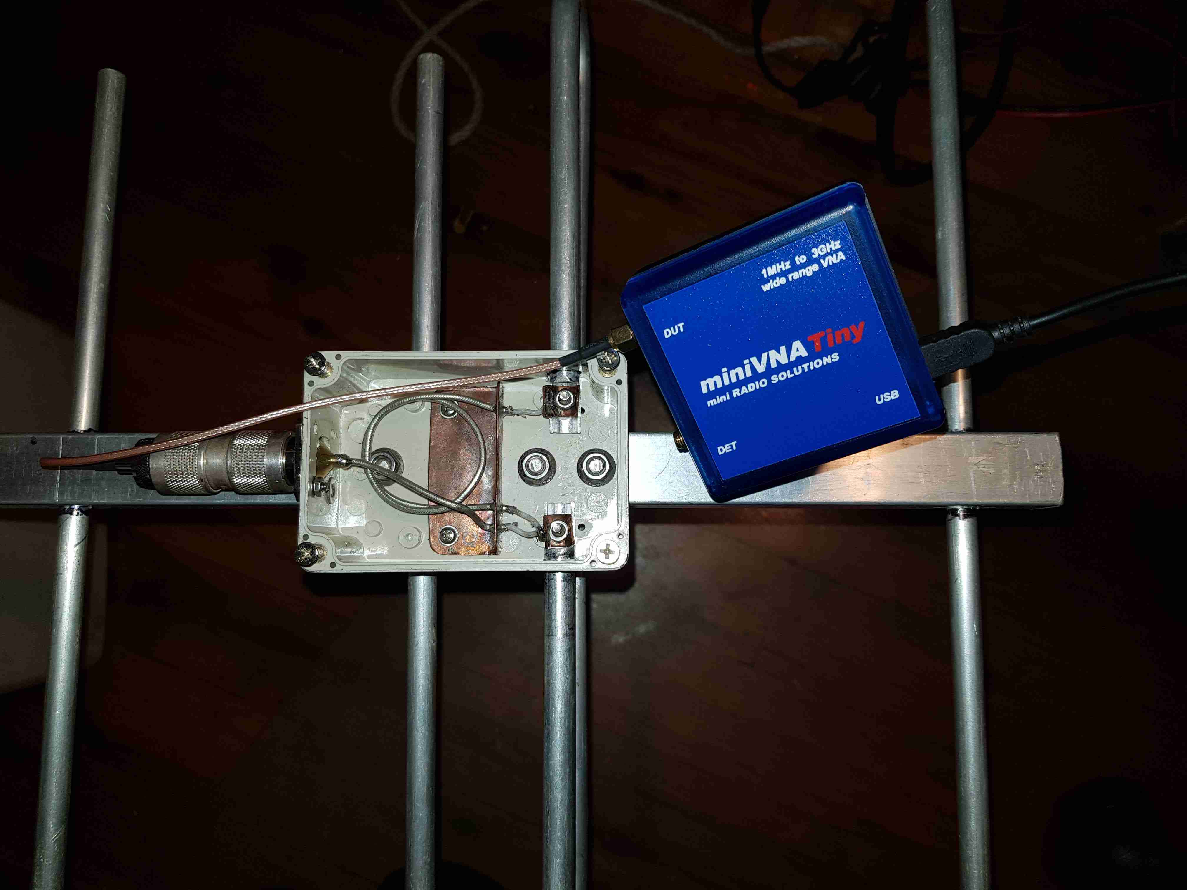
The RG405 is very stiff and I did somehow get a broken joint between the RG405
inner and one of the copper lugs. I must have snapped it when securing the bolts.
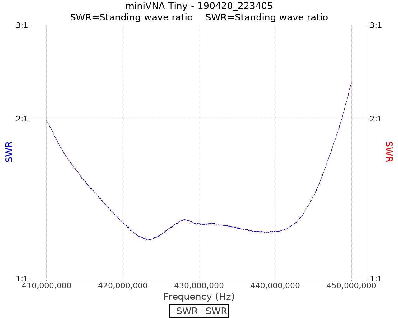
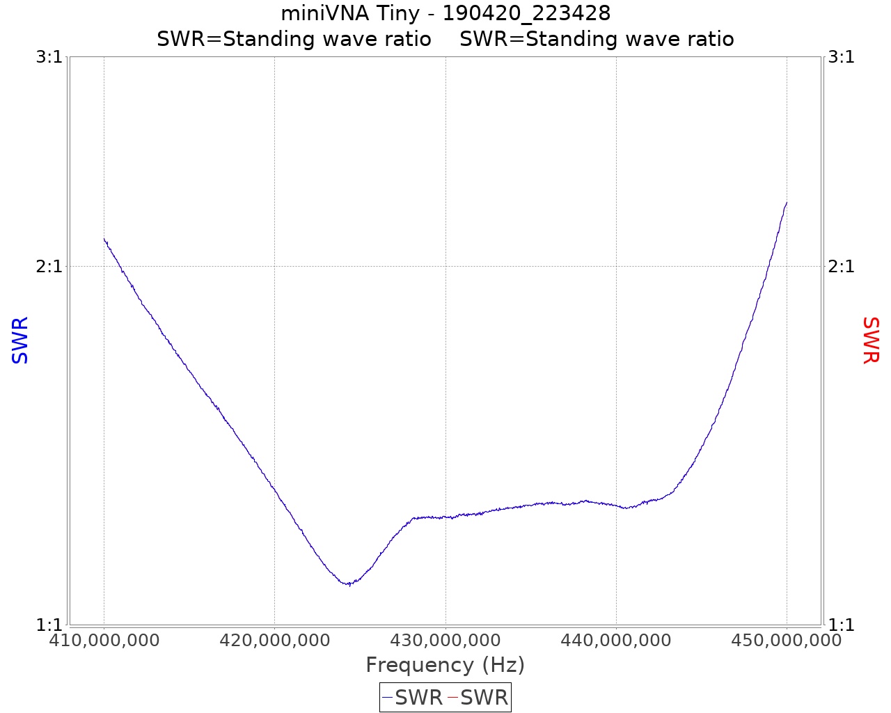
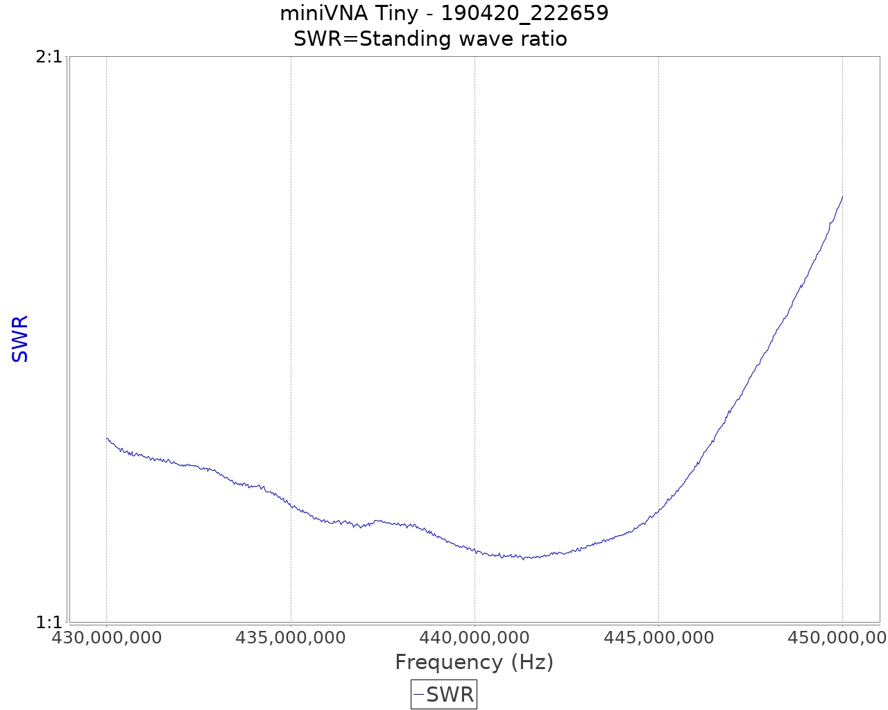
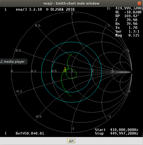
I had test it all with the ohm meter, but before bolting. The first VNA test
showed a resonate frequency of 2.5GHz. This had me perplexed for a while,
untill I applied first principals and tested again with the ohm meter.
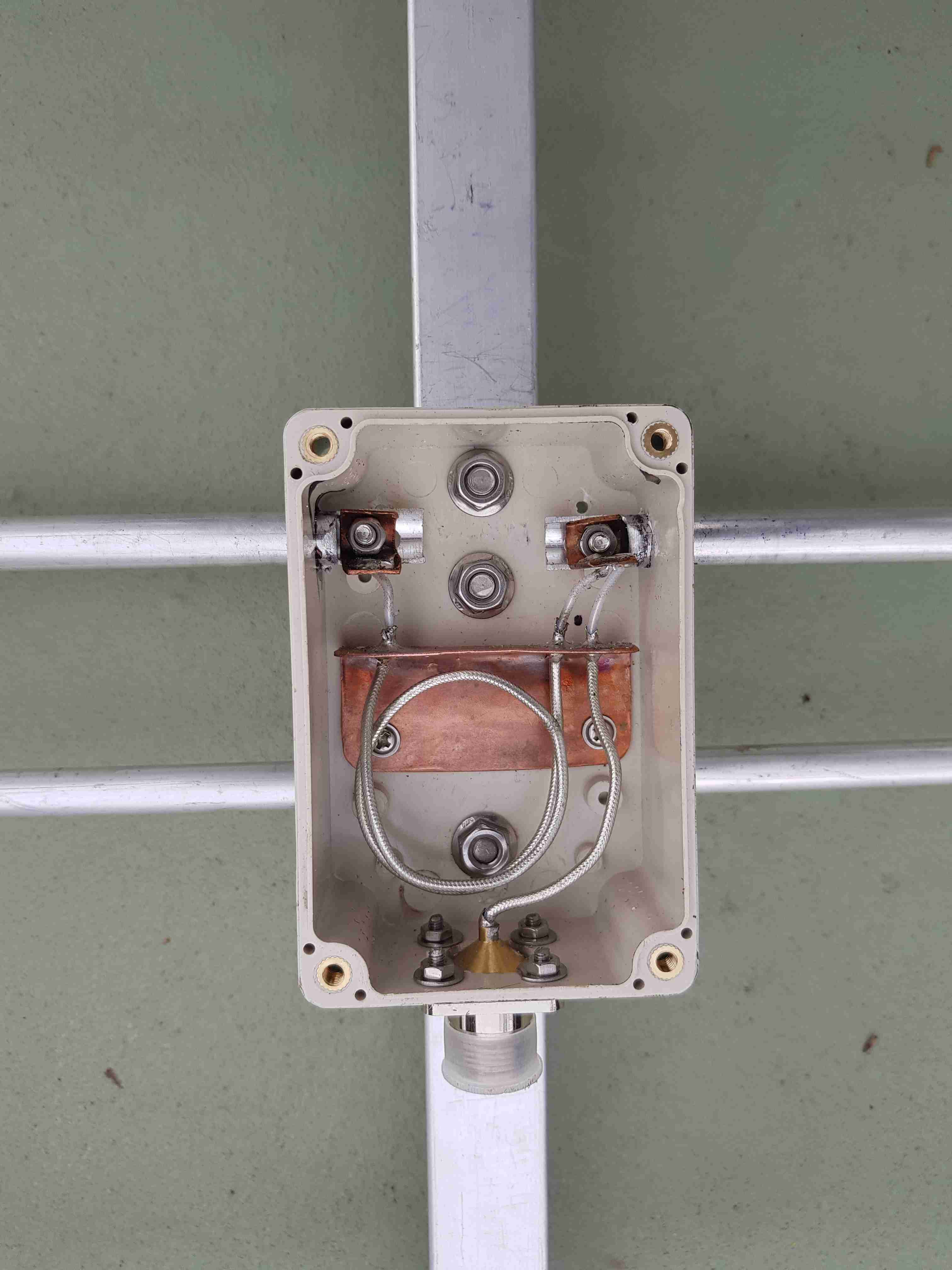
Before sealing with the lid, I applied some silicone cement to secure the balun
winding. they must remain in place during vibration and impacts.
[Top][Home]

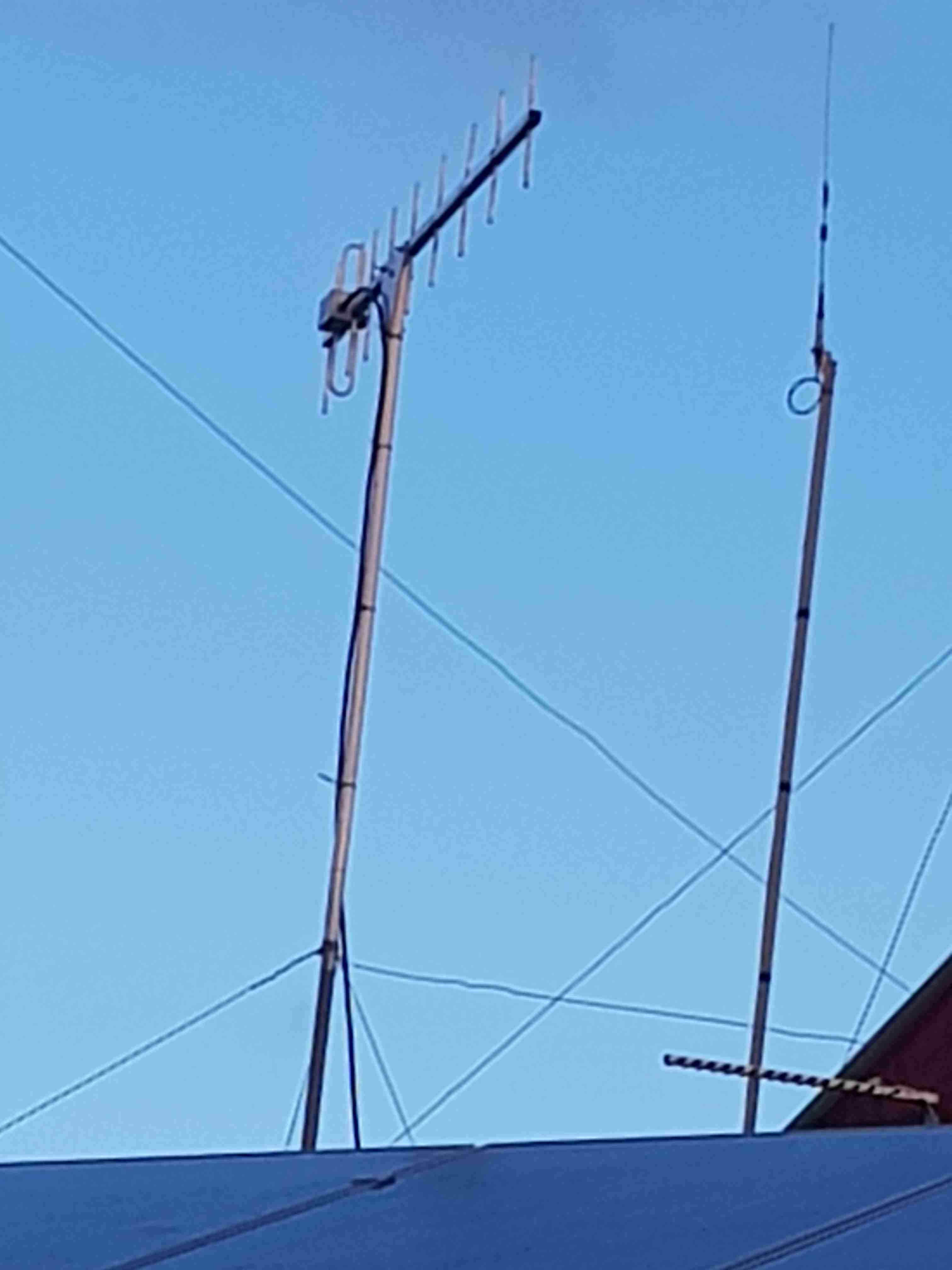
As most UHF antennas a vertical whips I decided to mount the bean with vertical
polarisation. That meant that the top section of the supporting post had to be
electrically non reactive. I used a meter length of 32mm orange conduit and
attached that to a four meter length of 32mm steel pole.
[Top][Home]
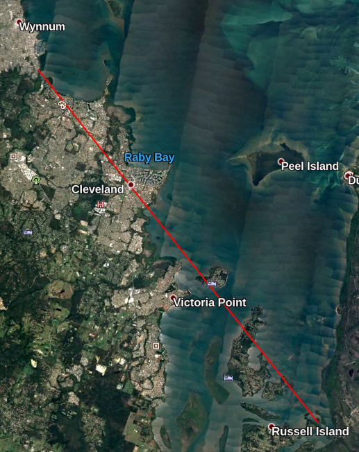
Google Earth was a good tool to determine a bearing from my location to
Cleveland is about 310 degrees "google-true" which I will assume is Grid North.
It could be a couple of degrees out but for this application it will surfice.
The Magnetic Variation is estimated to be about 11 degrees for this location.
The rule is to take the Grid bearing and SUBTRACT the Variation. So we
point the beam at apprximatly 300 degrees magnetic.
[Top][Home]