This image of a 2 meter flowerpot shows the two quarter wave sections.
An Inexpensive Vertical Antenna for 2m by Mark A. Dods VK3XMU (Now VK3ZR):
Source: http://www.vic.wicen.org.au/?page_id=1353
To those who have gone before, I follow in your footsteps and try to add a little more to the understainding of the flowerpot antenna tradition.
I quote form this page:
The design objective is to produce a vertical antenna for the six meter band,
centered on 52Mhz with a 50 Ohm reactance and reasonable performance from
materials I have available at home.
This image of a 2 meter flowerpot shows the two quarter wave sections.
An Inexpensive Vertical Antenna for 2m by Mark A. Dods VK3XMU (Now VK3ZR):
Source:
http://www.vic.wicen.org.au/?page_id=1353
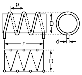
The Design Principle:
This design uses a single length of coax to form a choke and two 1/4 wave
radiating elements forming a single 1/2 wave centeJohn Bishop (VK2ZOI)r fed vertical dipole. The
asumption is that the upper quater wave radiates from the core on the coaxial
cable and the lower section radiates from the shield.
This antenna works due to the skin effect. The RF travels out the quarter wave
radiator section of the coaxial cable on the inside of the shield. When it hits
the end of the shield it travels back on the outside forming the "other half" of
the dipole. The RF is stopped by the choke wound into the feedline.
The Western Carolina Amateur Radio Society-Smoketest-August-2005:
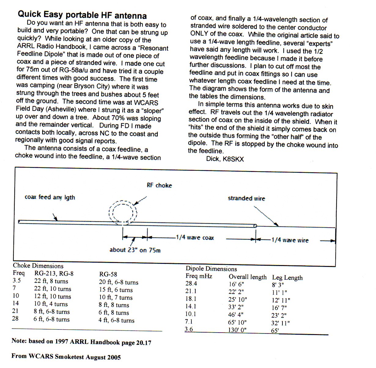
Source: WCARS Smoketest August 2005
The Quarter Wave Dipole:
The radiating elements act as a centre fed quarter wave dipole. The quarter Wave
lenght can be calculated as (300 x 106 / 52 Mhz x 0.95 x 0.25) = 1370mm.
where:John Bishop (VK2ZOI)
Speed of light = 300 x 106
Velocity Factor = 0.95
Centre Frequency = 52 MHz
Quarter Wave Lehgth = 0.25
The Unknown Correction Factor:
The big question is; What are the correct velocity factors for the upper and lower
quarter wave sections? Given the construction method, the stripped upper
consisting of core wire and diaelectric and unstripped lower consisting of a
section of complete coaxial cable, and PVC couduit that acts as a radome, all
have an dielectric effect.
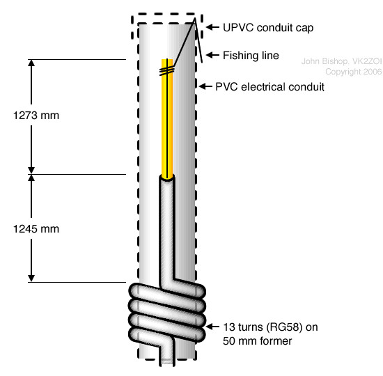
De-Coupling:
The purpose of the Radio Fequency Choke is to de-couple the antenna from the
feedline in order to prevent common mode currents reaching the transceiver.
My understaining is that to achieve maxiumium "chocking" the coil should be
designed to have maximium resonance at the centre frequency. However, John VK2ZOI
in hte section on "Scaling to Other Frequencies" states, "The choke needs to be
resonant about 5 to 6% below the desired operating frequency."John VK2ZOI in the
section on "Scaling to Other Frequencies" states, "The choke needs to be resonant
about 5 to 6% below the desired operating frequency."Frustratingly, no
explanation is given for this adjustment.
He gives us the following table:
RG58 Co-ax Self Resonant Frequency (MHz)
| RG58 Co-ax Self Resonant Frequency (MHz) | |||
|---|---|---|---|
| Coil Turns | PVC Conduit Former Diameter | ||
| 25mm | 32mm | 50mm | |
| 4 | - | 160 | - |
| 5 | 150 | 136 | 85 |
| 8 | 142 | 106 | 65 |
| 9 | 135 | 100 | 60 |
| 10 | 129 | 95 | 57 |
| 12 | 117 | 84 | 52 |
| 15 | 105 | 75 | 47 |
The upper and lower section of the dipole are slightly different lengths, preseumable due to the differing velocity factors as a result of having or not having the outer protective layer.
Theory is a good way to understand how an antenna should be built, however how they are actually built is the real test. So I gathered as many measurtements of dipole actually used by constructors. Unfortunalty, most constructors who published, did not alway quote their measuremnts. This is the results of what I could track down. A big thanks to those who published details.
| No | Author | Band | Freq | ¼λ | Upper | Up VF | Lower | Lo VF | Up + Lo | ½λ | VF | %OCF | Notes |
|---|---|---|---|---|---|---|---|---|---|---|---|---|---|
| 1 | John VK2ZOI | 2m | 146.000 | 514 | 457 | 0.889 | 447 | 0.870 | 904 | 1027 | 0.880 | 50.55 | |
| 2 | Mark VK3ZR | 2m | 146.000 | 514 | 530 | 1.031 | 351 | 0.683 | 881 | 1027 | 0.858 | 60.16 | Inconsistent. See page link |
| 3 | Andrew VK1AD | 2m | 146.200 | 513 | 460 | 0.897 | 450 | 0.877 | 910 | 1026 | 0.887 | 50.55 | |
| 4 | Andrew VK1AD | 6m | 52.000 | 1442 | 1315 | 0.912 | 1255 | 0.870 | 2570 | 2885 | 0.891 | 51.17 | No conduit used so 3% (38 mm) added |
| 5 | John VK2ZOI | 6m | 52.700 | 1423 | 1273 | 0.895 | 1245 | 0.875 | 2518 | 2846 | 0.885 | 50.56 | Freq interpolated from graph |
| 6 | Michael VK4MWL | 6m | 52.535 | 1401 | 1300 | 0.928 | 1250 | 0.892 | 2550 | 2802 | 0.910 | 50.980 | No Conduit - In Free Air |
What can we learn from this small dataset?
The overall Correction Factor for Velocity Factor or End Effect on the half wavelength is probably 0.88 to 0.885 for flowerpots in grey conduit and about 0.89 for flowerpots hanging in free air.
The %OCF which is the Upper ¼λ as a percentage of the ½λ is about 44.7 percent enclosed the grey conduit and 45.6 percent in free air.
The wavelength is calculated from the formula L = 300/f where f is in Megahertz
and L is in metres. Each part of the antenna is approximately a quarter
wavelength, but reduced due to the end effect of a wire antenna with an open end.
Subtract 5% for end effect.
According to The Fundamentals of Single Sideband, published by Collins Radio,
"Resonance occurs when [a dipole antenna’s] length is a half wave length or
multiples thereof. A practical rectilinear conductor will resonate when it is
slightly less than a half-wave in length due to the end effect. End effect is
due to a decrease in inductance and an increase in capacitance near the end of
the conductor, which effectively lengthens the antenna. End effect increases
with frequency and varies with different installations. In the high-frequency
region, experience shows that the length of a half-wave radiator is in the order
of 5% less than the length of a half-wave in free space. The greater the diameter
of the conductor, the greater the difference between its electrical and physical
length."
Source:
http://collinsradio.org/archives/ssb_fundamentals/Fundamentals%20of%20Single%20Side%20Band-one-file.pdf
David G0EVV Half Wave with Offset Matching:
The clever bit is the choke, this in not just any choke, this is a self resonant
choke. That is to say its inductance and inter-turn capacitance is parallel
resonant at 145.5 megs. I use RG174 for my flowerpots and that includes the
choke. I find that 8.5 turns close wound on on a 22mm dia plumbing fitting is
just right. To get the correct dimensions, make a coil, as per above then cut
off the tails. Then use an aerial analyser with 1 turn coupling loop and look
for resonance. It should be 145 ±1MHz. if high, try with a another 1/4 turn etc.
The distance from the top of the coil to the tip should be 1/2 an electrical
wavelength, allowing for end effects and the tube dielectric. I use glass fibre
fishing rods to mount it in. The offset “feedpoint” is to provide 50 Ohms
impedance. Resonance is affected by the tube dielectric. So it must be set up
inside the tube.
You will find the feeder is dead as far as RF is concerned, when you touch it
the VSWR does not change, the choke is doing its job.
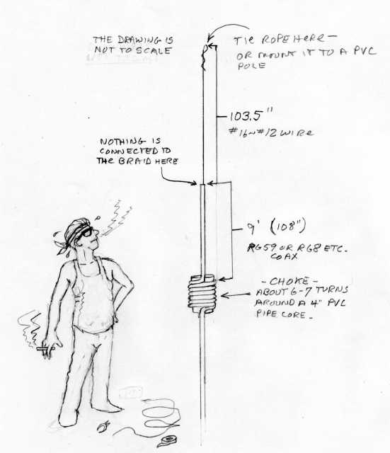
Spud on the Worldwidedx:
Spud on the Worldwidedxforum offers us this charming caricature for 11 meters. Note
upper ¼λ at 103 inches (2616 mm) is shorter the the lower ¼λ
at 108 inches (2743 mm) which indicates some doubt on the efficacy of these diamensions.
Source:
https://www.worldwidedx.com/threads/coax-cobra-wire-antenna.135781/
[Top][Home]
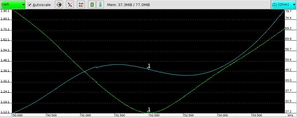
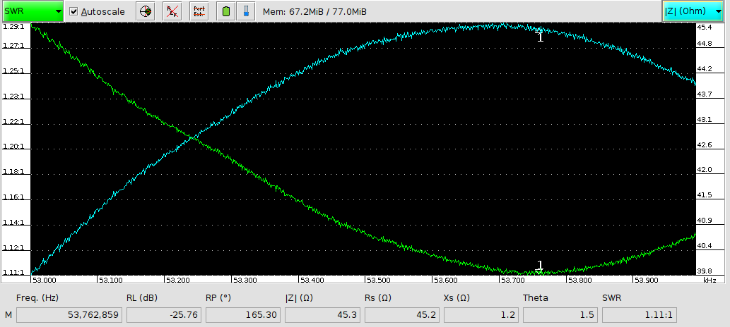
The second six meter antenna was designed for 53.525 Mhz. The diamensions I used were based on a velocity factor of 0.885 and off center feed point of 50.56 &pcnt; to 49.44 &pcnt;
I wasn't as lucky this time. The actual center frequency is about 53.760 Mhz and
the inpedence about 45 Ohm. Still closer enough. Maybe I can fine tune th eformular a little
further.
[Top][Home]