The Butternut has been optimized directly on the roof with SWRV close
to 1:1 in all bands by means of an MFJ analyzer at the base, acting on the
physical element-inductance length and with the "cut & try" method for adjusting
the wire counterpoise elements . From theory we know that the ground losses of
a 1/4 wave GP with 4 radials, placed at least at 1/2 a wavelength off the real
ground, has an efficiency comparable to the same vertical placed directly on the
ground with 120 radials.
""
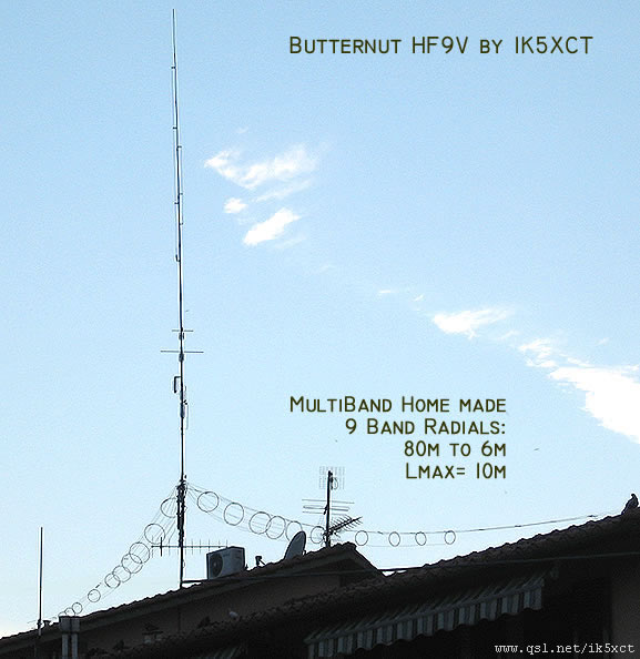
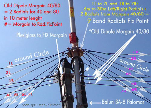
The IK5XCT installation has two radials 1/4 wavelength from 40 to 6 meters,
and two radials 1/8 loaded linearly for 80 meters, all gathered in two opposite beams
at 180 degrees. This will make the radiation lobe slightly oval in the missing
directions with respect to at least 3 or 4 radial bundles.
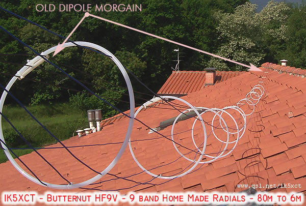
In the photo you can see the wires marked from 1L to 7L for the left side and
from 1R to 7R for the right.
These loops were then drilled with 3mm holes to pass 1.5mm wire through
to acts as a radial. On the first ring 7 holes must be drilled at a
constant distance so that the length of the string between one and the other is
about 15cm .. 15cm will also be the measurement between the nearest hole and the
original morgain antenna that is now repurposed as a counterpoise.
The purpose of the loops is to spaces the radials apart as an alternative to the
traditional fan arrangement. These loops get progressively smaller as
less and less radial remain.
As the loop progress away from the dipole:
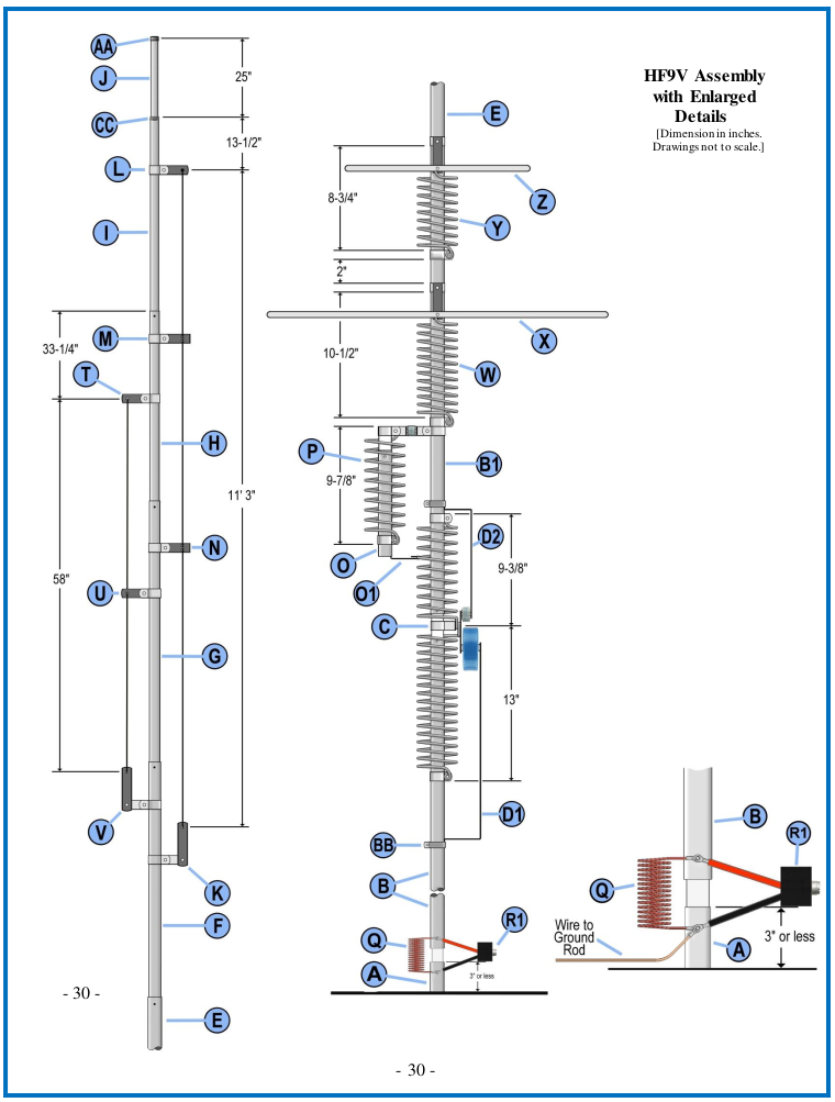
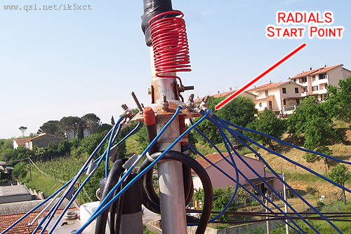
A radial fixing plate manufactured to connect the original 80 and 40 meter radials and the 7 higher frequency radials.
So maybe the 40 / 80 radials are tuned counterpoise in the Morgain folder pattern and tuning the Morgain Antenna Counterpoise procedure consist in moving the jumpers AA for the 80 meters, and jumpers BB for the 40 meters. To calibrate , prepare 4 wire jumpers , 12 cm long, with connecting pins at the ends. You start by inserting the pins ( with the relative jumpers ) in the lenghts listed, then raise the antenna in the working elevation and trace the SWR. If this is not acceptable, move the jumpers a little at a time until you will reach an SWR close to 1:1. At this point, after having taken notice of the exact distances, replace the jumpers with new jumpers that will be soldered and insulated . You will notice immediately , from the first movements that there is a significant interaction between the calibration of 80 m and that of 40 m, so make tuning by for short distances.