Note: Licence Required
SmartSDR v2 requires a software license installed on the radio before it can be
used with a FLEX-6000. All radios sold after May 19, 2017
All other radios require the purchase of a software license for the radio.
Please see the section “Purchasing a SmartSDR Software License for your FLEX-6000”
for instructions on how to purchase a license
[Top][Home]
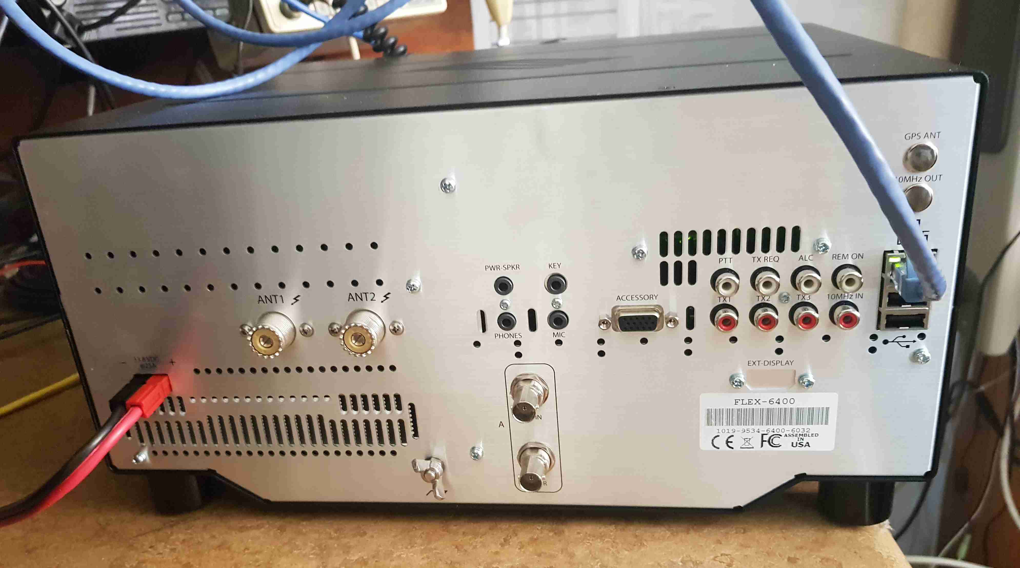
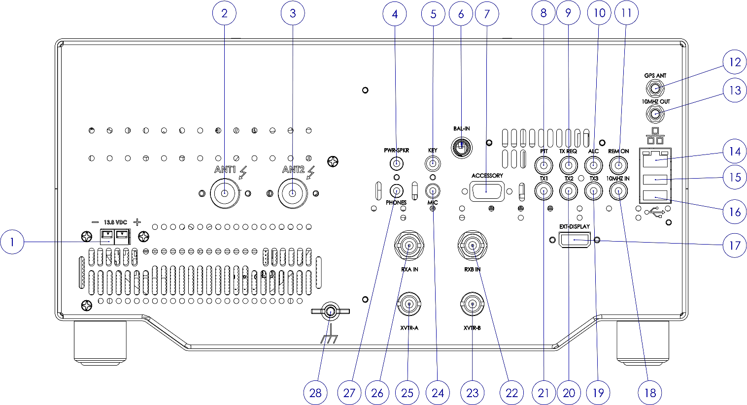
The FLEX-6400 radios incorporate a unique smart antenna switching
matrix to simplify connections from the radio to station antennas.
ANT1 and ANT2 can be used for transceiver operation.
The XVTR ports can be used for transverter operation or as an
additional receive antenna port.
[Top][Home]
The transverter translates RF at one frequency to
another for both transmit and receive. Generally, the transverters will have an RF side
that is in the VHF or microwave region and an IF side in the HF or low VHF side. An
example transverter block diagram is shown below:
This transverter converts from 10m RF signals (28MHz) to 1296MHz RF signals and back.
The transverter shown in the picture has three RF connectors:
RX IF - the 10m receive port
TX IF - the 10m transmit port
RF - the RF input and output that goes to an antenna
This type of transverter is known as a “Split IF” transverter since the IF side of the
transverter utilizes both a receiver and a transmitter port. The other type of transverter
is a “Common IF” transverter where a relay internal to the transverter is used to switch a
single IF port between receive and transmit. Both the FLEX-6400 and FLEX-6600 are
capable of either Common IF or Split IF operation.
Page 35 of 45
Copyright 2018 FlexRadio Systems. All Rights Reserved.FLEX-6400/FLEX-6600 Hardware Reference Manual
https://www.flexradio.com/downloads/flex-6400-and-flex-6600-hardware-reference-manual-pdf/?wpdmdl=3104&refresh=5c9310c8c78ae1553141960
10.1 TRANSMIT POWER CONSIDERATIONS
The default transverter output is 0 dBm (1.0 mW). The FLEX-6400/FLEX-6600 can produce an output on the XVTR port up to +15dBm for frequencies below 54MHz. If your transverter requires a higher-level input, it is recommended that you either modify the transverter for a lower power input or provide an amplifier to amplify the transmit signal before passing to the transverter.
10.2 RF CONNECTIONS - COMMON IFFor a common IF configuration, the Common IF port of the transverter should be connected to the XVTR port on your FLEX-6400/FLEX-6600. This will be the only RF connection between the transverter and the radio.
10.3 RF CONNECTIONS - SPLIT IFFor split IF transverters, the TX IF of your transverter should be connected to the XVTR port on the FLEX-6400/FLEX-6600. The RX IF port should be connected to either RX-A or RX-B (FLEX-6600 only). While it is technically feasible to use the ANT1 or ANT2 ports for receive, this is not recommended since these ports can produce high-power RF at any time that could damage your transverter.
10.4 PTT CONNECTIONSThe radio will need to provide a PTT signal to place the transverter into transmit mode. Most transverters will have a grounded-PTT input. This should be connected to a FLEX- 6400/FLEX-6600 TX1, TX2 or TX3 output to cause the transverter to transmit. Depending on the design of the transverter, a weak pull-up may be required. 10.5 SEQUENCERS
In some transverter applications, notably those that include a split RF output, preamplifiers and/or power amplifiers, a sequencer may be used. The specific details of connecting and configuring a sequencer are beyond the scope of this document, but the TX1, TX2 or TX3 output from the radio are generally used as an input to the sequencer to allow it to properly switch and enable/disable each component in your lash-up.
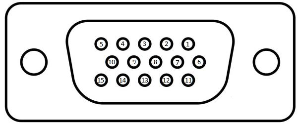
This audio line input can be used to feed consumer level (-10dBV) audio into the transmitter. Refer to the SmartSDR documentation for information describing how to enable this input, and what configurations are available.
This audio line output is a buffered output of the POWERED SPEAKERS left channel.
This input is a keying input for CW. Refer to the SmartSDR documentation for information describing how to enable this input, and what configurations are available. Pin 4 is keyed to GROUND. See Page 23 of 45 Copyright 2018 FlexRadio Systems. All Rights Reserved.FLEX-6400/FLEX-6600 Hardware Reference Manual
This pin is a +5VDC output for use by external equipment. This pin is capable of sourcing up to 500mA of current. A thermally resetting fuse will protect the radio from damage. I - This pin is protected by a thermally protected fuse. If an over-current occurs, the fuse will open and remain open until the overload is removed.
This pin is a buffered PTT output identical to the three RCA connectors TX1, TX2, and TX3. Refer to the SmartSDR documentation for information on how to configure this output.
This pin is the data signal for an I2C serial communication channel. It is to be used with external equipment. Refer to the SmartSDR documentation for more information.
This pin is an additional transmitter interlock signal input. documentation for information on how to configure this input. Refer to the SmartSDR
This pin is a Push-To-Talk input. Ground Pin 14 to engage transmit.
This pin is the clock signal for an I2C serial communication channel. It is to be used with external equipment. Refer to the SmartSDR documentation for more information.
This RCA connector is provided for an external Push-To-Talk signal.
Ground the center pin of this RCA to engage PTT. (Note: 3.3VDC Max. Input.)
![]() 7.8 TX REQUEST INPUT (INTERLOCK)
7.8 TX REQUEST INPUT (INTERLOCK)
This RCA connector is provided to receive an interlock signal from external amplifiers, or other external equipment. When enabled it will prevent the FLEX-6400/FLEX-6600 from Page 24 of 45 Copyright 2018 FlexRadio Systems. All Rights Reserved.FLEX-6400/FLEX-6600 Hardware Reference Manual going to transmit. The TX Request Input can be enabled with a 3.3V to 5V logic signal (when in Active High mode) or connecting to ground (when in Active Low mode). The circuit is a 74LVC14 CMOS Schmidt trigger logic input with a 2.7k pullup to +3.3V. The IC is 5V tolerant, so you can drive it with TTL levels as well. It can also be driven with an open collector transistor or open drain MOSFET. Grounding the center pin of this connector will prevent transmit from engaging (when in Active Low). Refer to the SmartSDR documentation for information about how the interlock system works and how to determine what is preventing transmit. The SmartSDR for Windows Software User’s Guide also includes details on how to interlock two radios from simultaneous transmit for a Multi/2 operation.
This RCA connector is provided to receive an ALC signal from an external amplifier. The shell is ground, and the pin is a negative going DC voltage, zero to -4 Volts. ! – VOLTAGES BELOW -4VDC MAY DAMAGE THE ALC INPUT. Δ – Please note this input is provided as a safety measure for external amplifiers. It is NOT meant to be used in regular operation as an active power control input or to modify the “attack” of an external amplifier. Almost all modern HF amplifier manufacturers discourage the use of ALC in normal operation. In fact, many amplifiers do not have ALC implemented. The SmartSDR Software User’s Guide describes the recommended method for setting the power level on an external amplifier on a per- band basis.
7.10 REMOTE POWER ON INPUT This RCA connector is provided for remote power-on functionality. When the Remote Power ON feature is enabled, shorting this input to ground will activate the radio - opening this connector will disable power on the radio. Refer to the SmartSDR documentation for information on how to configure this input. (Note: 3.3VDC Max Input.)
If the radio is equipped with the optional GPSDO, this female SMA connector is for connecting the included GPS antenna. The GPSDO provides DC bias for the antenna preamp. It can work with antennas that require either 3.3 Volt or 5 Volt DC bias.
If the radio has the optional GPSDO, the 10 MHz reference output is a buffered 3.3V p-p
output of the 10 MHz oscillator in the GPSDO. The signal can be used to provide a
reference signal for external equipment. The connector is a female SMA.
Page 25 of 45
Copyright 2018 FlexRadio Systems. All Rights Reserved.FLEX-6400/FLEX-6600 Hardware Reference Manual
CAUTION: USE CARE IN ATTACHING OR REMOVING SMA CONNECTORS. BEST
PRACTICE IS TO HOLD THE COAX WITH ONE HAND WHILE TWISTING THE SMA
CONNECTOR SHELL WITH THE OTHER. ONCE THE MALE AND FEMALE CONNECTORS
MATE, TURN UNTIL SNUG BUT DO NOT OVER TIGHTEN!
auto-sensing 100 megabit or gigabit Ethernet port. auto-senses polarity as well allows direct connection to a PC
The USB 2.0 ports are used for SmartSDR specific functions only. Do not connect unqualified USB devices
External displays are not supported on FLEX-6400 and FLEX-6600 models.
The external reference clock input is used to synchronize the radio’s master oscillator. Requires a 1.0v p-p minimum to 3.3v p-p maximum (4dBm min - +15dBm max), sine or square wave signal.
The radio can use the external 10MHz reference, the optional GPSDO reference, the
internal TCXO reference, or choose among them automatically. When set to automatic
mode, the radio prioritizes the reference signals in External, GPSDO and TCXO order. In
automatic mode, the radio watches for the appearance or disappearance of reference
signals and chooses the highest priority available signal. In manual mode, the radio uses
the selected input whether a signal is present or not. See the SmartSDR documentation
for more details.
![]()
![]()
![]() 7.17 TX RELAY OUTPUTS [1,2,3]
7.17 TX RELAY OUTPUTS [1,2,3]
TX1, TX2 and TX3 are outputs for keying external equipment such as amplifiers, external
T/R switches, etc. They are isolated individual outputs. Refer to the SmartSDR
documentation for an explanation on how to configure the timing for each output.
Page 26 of 45
Copyright 2018 FlexRadio Systems. All Rights Reserved.FLEX-6400/FLEX-6600 Hardware Reference Manual
NOTE - The TX Relay outputs are designed to handle signaling levels of up to +40 VDC @ 140
mA maximum. Some amplifiers do not have circuits to prevent keying voltage
transients and older amplifiers may exceed the maximum voltage level resulting in
damage to the radio if directly connected. Verify the voltage/current on your external
device before connecting to TX Relay 1-3. FlexRadio highly recommends the use of a
use a buffer/isolator box between the radio and the external device as a best operating
practice regardless of the keying voltage.
This female BNC connector is a direct feed to the input of the second Spectral Capture Unit (SCU-B) in the radio. This port is for use as a RECEIVE ONLY input to the RXB SCU. Refer to the SmartSDR documentation for information describing how to select this input, and how it can be used.
This female BNC connector is a receiver input and low-level exciter output for use with
Transverters. Refer to the SmartSDR documentation for information regarding using the
FLEX-6400/FLEX-6600 with external transverters. The FLEX-6400 has one transverter port
and the FLEX-6600 includes two transverter ports.
NOTE - The XVTR port can also be used as an auxiliary receive antenna connection when not
being used for transverter operation.
The MIC connector accepts a 1/8-inch (3.5mm) stereo (TRS) plug and provides a pseudo-balanced microphone input. Pseudo-balanced means that the mic (+) and mic (-) lines are balanced all the way to the input of the A/D converter, where the mic (-) line is DC grounded. The connector may be used with dynamic or electret microphone elements. A software enabled 3V bias voltage through a 2.1k Ohm source impedance may be applied to the Mic (+) line for electret microphones. Note: The PTT signal is not accepted by this connector.
This female BNC connector is a receiver input and low-level exciter output for use with Transverters. Refer to the SmartSDR documentation for information regarding using the FLEX-6400/FLEX-6600 with external transverters. The FLEX-6400 has one transverter port and the FLEX-6600 includes two transverter ports. I - The XVTR port can also be used as an auxiliary receive antenna connection when not being used for transverter operation.
7.22 RX IN/RX-A RF INPUT This female BNC connector is a direct feed to the input of the first Spectral Capture Unit (SCU-A) in the radio. This port is for use as a RECEIVE ONLY input to the RXA SCU. Refer to the SmartSDR documentation for information describing how to select this input, and how it can be used.
The PHONES connector accepts headphones with a standard 1/8-inch (3.5mm) stereo
(TRS) plug. Recommended ratings for headphones are 25mW into 16-ohm load or 13mW
into a 32-ohm load. CAUTION: Do not use a mono (TS) plug as this will short-circuit the
right channel signal to ground.
WARNING! NEVER operate the transceiver with headphones or other audio accessories
at high volume levels. Discontinue use immediately if you experience any ringing in
your ears.
This is a thumbscrew for attaching an earth ground to the chassis of the radio. Grounding is the most important safety enhancement you can make to your shack. Always ground the FLEX-6400/FLEX-6600 to your station RF ground using high quality wiring with the length being as short as possible. Braided wire is considered the best for ground applications. Your station ground should be a common point where all grounds come together. You will likely be using a PC and a DC power source so be sure to ground these devices together as well.
The relay acts just like pressing the power switch. The radio does its normal boot-up and shut-down routines. You need to have 13.8V applied before closing the relay, and keep it on after opening the relay until the radio has shut down.
Linear power supplies take an AC input (typically 120VAC or 240VAC), step down
the voltage with a transformer, then rectify and filter the input into a DC output.
The linear power supply is typically less efficient, uses a bigger transformer
as well as bigger filter components. They are heavier and can hum
from transformer laminations resonating if not well constructed.
A switching power supply takes an AC input, but rectifies and filters into DC
first, is converted back into AC at some high switching frequency, steps down
the voltage with a transformer, then is rectified and filtered into a DC output.
The switching power supply implies higher efficiency due to the high switching
frequency, enabling it to use a smaller, less-costly high-frequency transformer
as well as lighter, less-costly filter components. Switching power supplies
contain more overall components, therefore are usually more expensive.