QRP Manual Antenna Turner Unit
Contents:
- Manual Antenna Tuner Package Assembly Instructions
- Alternative Product - Emtech ZM-2 ATU
[Top][Home]
Product Description
Days can tune to the original non-resonant antenna by adding the appropriate
inductance or capacitance so that the radio can work properly. The original
resonant antenna, the antenna has changed due to outside influences, the SWR
can be amended. Can be used as a band-pass filter, the emission can reduce
unnecessary radiation outside the band, the cross-modulation and
interference-band receiver can be reduced again.
Days tune kit comes with the standing wave directions, using a T-type topology
network, shortwave 1-30MHz, can withstand the transmit power of 15W, the tuning
range of approximately 40-300 ohms, can be very convenient for QRP
communication, to ensure high efficiency radio transceiver in communication,
but also allows you to fully enjoy the fun of DIY.
This kit requires some soldering electronic technology, will recognize the
device, it will weld, the basic need debugging, as long as careful assembly
according to package instructions can succeed. If the novice find weld on the
error, intended to build the first not handle, please contact customer service
personnel will get the appropriate technical guidance.
This kit welding, making easy to understand, easier to learn, easy to use.
Comes with standing instructions, Q9 type interface (such as the need to be
self to M-type interface), using T-topology networks, QRP facilitate
communication with the low-power transceiver (shoes, frogs, octopus, etc.)
used to make transceiver and antenna valid match, meet your emission
requirements, ensure a highly efficient radio communications.
Features:
- Days when exposed to direct transfer power: less than 20W
- Day tune tuning the input power: less than 3W
- Tuning indication: LED display
- Interface: Q9 type
- Operating frequency: 1-30MHz
- Antenna Interface: Q9 type
- Match the antenna impedance range: about: 30 ~ 300Ω
- Carrying RF power: less than 15W
- Tuning required RF power: less than 3W
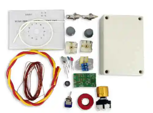
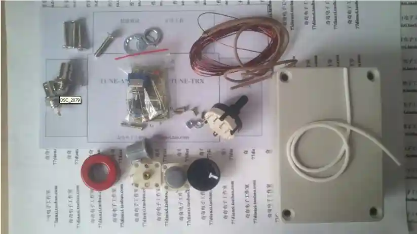
Kit Components:
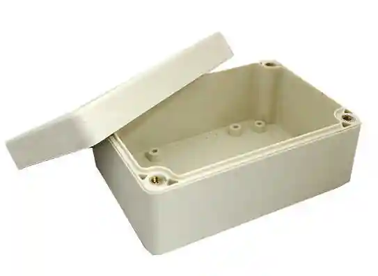
- A waterproof sealed box
- Stickers (used to determine the position of the transfer hole) 1
- Q9 Block lug (BNC) 2
- Ordinary wire segment
- Variable capacitor 2
- Small knob 2
- 0.25 countersunk head screws (for fixed variable capacitor) 4
- The 0.25 head screws 2
- 0.3 gasket 4
- 0.3 nut 2
- Multi-knife switch (12 stalls) with a large knob
- T106-2 the toroid (red) 1
- 0.5 enameled wire, Section 1,
- A circuit board (standing wave indicator)
- A stall switch
- The red light emitting diode 1
- 51 ohm 2W resistor 3
- FT37-43 toroid (Black) 1
- 1K resistor (light-emitting diode current limit) a
- 1N60 1
- 0.1u capacitor 1
[Top][Home]
Manual Antenna Tuner Package Assembly Instructions
Days can tune to the original non-resonant antenna by adding the appropriate
inductance or capacitance so that the radio can work properly. The original resonant
antenna, the antenna has changed due to outside influences, the SWR can be
amended. Can be used as a band-pass filter, the emission can reduce unnecessary
radiation outside the band, the cross-modulation and interference-band receiver can be
reduced again.
Days tune kit comes with the standing wave directions, using a T-type topology
network, shortwave 1-30MHz, can withstand the transmit power of 15W, the tuning
range of approximately 40-300 ohms, can be very convenient for QRP
communication, to ensure high efficiency radio transceiver in communication, but
also allows you to fully enjoy the fun of DIY.
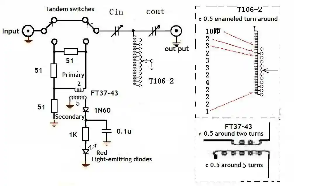
Schematic
Study the schematic diagram carefully before commencing production.
The following picture shows the circuit diagram.
The two insert figures on the right detail the coil woudnings.
Assembly
- Tools required are soldering iron, solder wire, scissors, knives, drills, wires.
The following picture shows the package contained in the device.
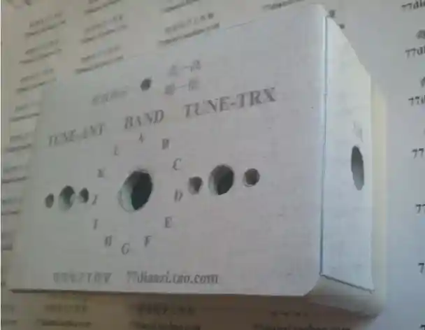
- The stickers show the position of drilled holes.
Pay careful attention to the variable capacitor
holes.
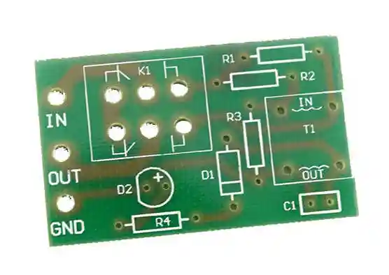
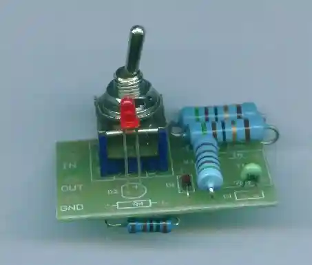
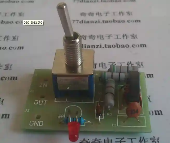
- First solder in the standing wave detection circuit and light-emitting diodes and toggle
switches installed
This operation is the first production of finished F37-43 transformer. FT37-43 and
other standing wave detection device soldered in a toggle switch on the panel,
note volume without soldering too much!
After soldering, the effect is as follows strict reference schematic and wiring
diagram produced.
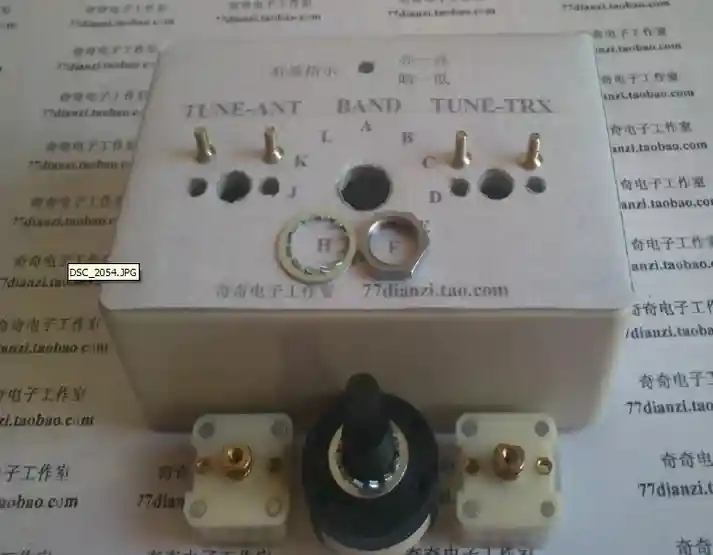
- 4, installation of variable capacitors and multi-knife switch. As shown below to
prepare materials, installed as shown below
- 5, welding multi-tool switch
The first step, the production of inductors, to complete the effect
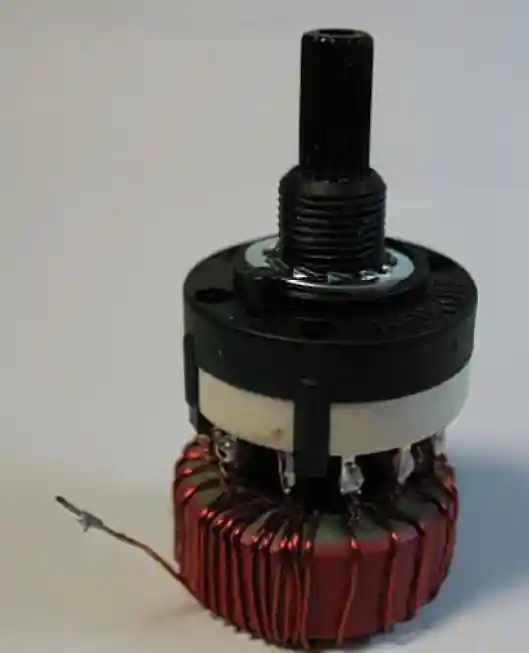
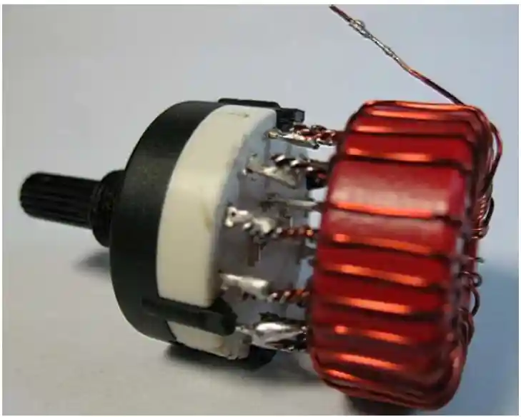
Pay attention to the winding direction and turns, maintain and schematic!Remove
the knife switch, complete and inductance of the welding, the effect is as follows,
the details of the plan


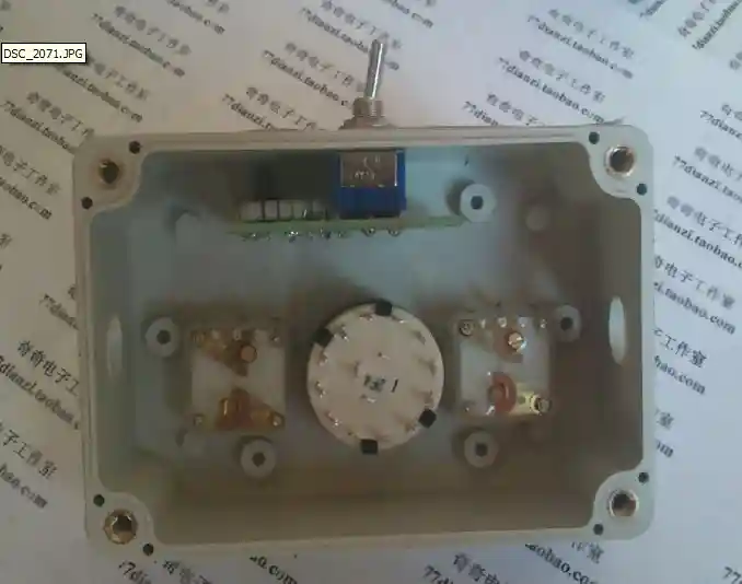
The combination of a good knife switch and inductor into the panel.

- 6 installation capacitance knob


- 7, wiring assembly, in accordance with the principles of wiring, refer to the
diagram

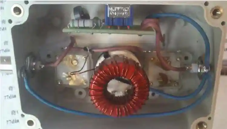
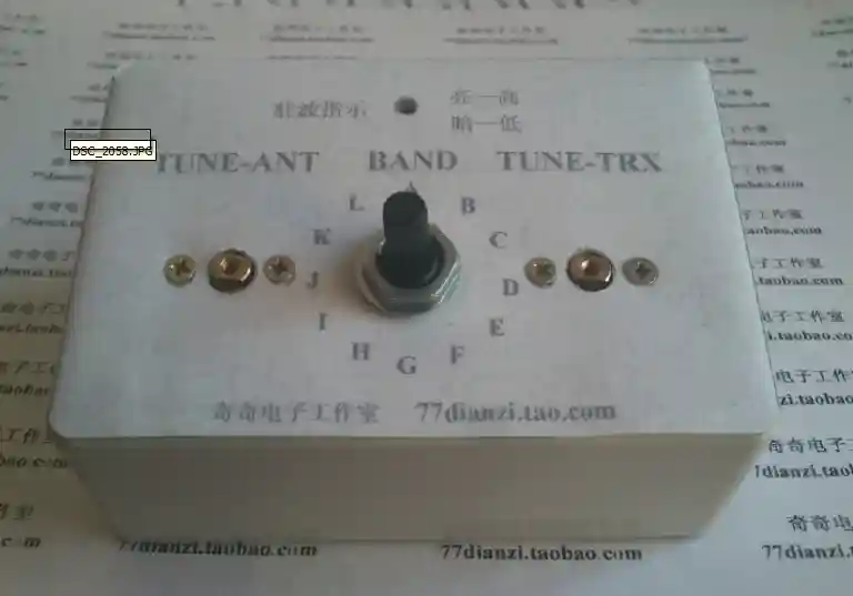
The Finished Product:
Operating:
Key allocated to the standing wave test, connected to the transmitter and
antenna.
2 according to key the transmitter (SSB machine to make a call), repeated
to adjust inductance knob and two capacitors knob, until the red LED
brightness minimum stop tuning.
3 Key allocated to the normal use, to complete the tuning of the antenna.
(Kit built-in dummy load VSWR test the maximum input power of 5W,
not long to launch)
Note:
1 adjusting the tuning range of about 40-300 ohms, other parameters, if
necessary, change the number of turns of T106-2 to adjust.
2 Standing wave test, the input power tune Do not exceed 5W, not a long
test.
[Top][Home]
Alternative Product - Emtech ZM-2 ATU

https://steadynet.com/emtech/zm2-prebuilt-bnc-connectors
[Top][Home]
[Top][Home]
Glenn Lyons VK4PK
glenn@LyonsComputer.com.au
Ver:gnl20190218 - pre published v0.9