The 27.5-ms frame consists of a total of 264-bits; 108-bit payload, 48-bit SYNC or
embedded signaling, and a second 108-bit payload for a total of 216-bits of
payload per frame.
The vocoder must compress 60-ms of audio with FEC (forward error correction) into
216-bits of data for transmission.
The 2.5ms-gap is used for guard time to allow PA ramping and propagation delay


| Dibit | Frequency Encoding |
|---|---|
| 01 | carrier - deviation |
| 00 | carrier - (1/3)*deviation |
| 10 | carrier + (1/3)*deviation |
| 11 | carrier + deviation |
4FSK modulation can be expressed using following equation.
S(t) = Ac*Cos[2*π(Fc+Δf)*t]
Where in 4 different Δf as shown in the table are used to represent 4 diferent
binary dibits in 4FSK to achieve corresponding outputs.
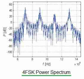
The figure depicts a 4FSK power spectrum. There are 4 carrier peaks in 4FSK modulation.
This is due to the fact that data are represented by 4 carrier phase shifts in the 4FSK.
DMR has a 2.5mS Guard Slot between the time slots that different
transmitters can use. The guard slot is the gap between the end of one time slot
and the beginning of another.
1.5mS of the Guard Slot is used for ramp up at the beginning of a
slot, and ramp down at the end, leaving only 1mS true quiet time. There is also
the issue that the clock frequencies running the Digital Signal Processors (DSP)
in Transmitter A and Transmitter B may be different, so the respective transmissions
could start slightly earlier or later than they ideally should. Typical DSP Clock
accuracy accounts for another 0.5mS, so the true guaranteed quiet period between
adjacent DMR TDMA slots is only 0.5mS.
If one transmitter more distant, the propagation delay is longer.
Eventually the signal from a closer transmitter will be received before the delayed
signal from the distant transmitter has finished and as the signal from closer
transmitter is much stronger, the end of the transmission from more distant
transmitter is lost. All things being equal it is generally assumed that this
occurs at aout 110 to 140 Km