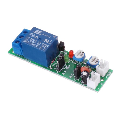
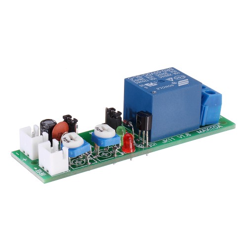
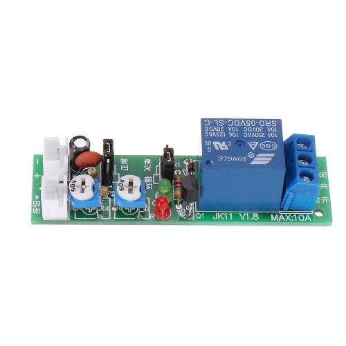
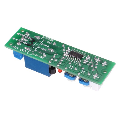
JK11 Adjustable Cycle Timer Delay
Specifications:
- Voltage: 5V DC
- Quiescent current: 8mA
- Operating current: 95mA
- Trigger: passive switch trigger, response time is 0.03 seconds (the trigger terminal can not access the active signal)
- Minimum on-off time: 0.2 seconds
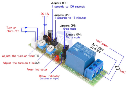
- Load Capacity: 10A 250VAC, 10A 30VDC
- Output form: normally open + normally closed
- Size: 70*20*19mm
- Using industrial-grade single-chip microcomputer to control time, high
precision and stable performance;
- Two adjustable resistors are used to adjust the time, and the connection
duration and the disconnection time can be independently adjusted;
- The external contact is activated, and the timing is started by shorting the
self-reset button. It is also possible to start the countdown by shorting the
triggers together to achieve power-on;
- The time range is divided into 0-100 seconds, 0-15 minutes, and 0-30 minutes.
Basic working principle:
Taking the factory standard setting as an example, the red LED will light when
the power is turned on, and the relay is in the off state. When shorted at the
trigger end, the module green light is on and immediately enters the working state.
Triggering again in the working state will stop working.
In the working state, the relay will pass T1 seconds, break T2 seconds, pass T1
seconds, break T2 seconds… infinite loop. T1 T2 is the length of time the user
adjusts with an adjustable resistor.
Instructions:
 Power access:
The module is connected to the power supply according to the correct power supply
voltage and polarity. The red line of the power supply terminal is positive and
the black line is negative.
Trigger line access:
The two white lines of the trigger end are connected to a switch, and the module
can be started by tapping the switch, and then the switch is stopped by tapping
the switch. The trigger switch can be a tact switch, a micro switch, an
optocoupler C-E terminal, a relay contact, and the like.
Normal speed and quick mode settings:
The OP1 jumper is used to select normal speed and fast mode, and the shipment
defaults to normal speed.
Loop mode and single mode settings:
The OP2 jumper is used to select the loop mode and the single mode, and the
shipment defaults to the loop mode.
Cycle mode: After starting, the relay is on-off-on-off-disconnect…, and it is
cycled according to the set duration;
Single trigger: After starting, the relay is turned on, and the relay is turned
off after T1 duration. (After disconnection, the action ends and waits for trigger again)
Precautions:
- The module power supply is not protected against reverse protection, because
it is important to remember that the power supply cannot be connected.
- The trigger terminal can only be connected to the passive switch, not to the
voltage signal. Doing so can damage the module.
- When the resistance load is connected, no special treatment is needed; when
the capacitive load is connected, the relay module is easily damaged by electricity. It is recommended to use the AC contactor derated or the contact current of the motor should be considered within 10A.
- Borad Number: (marker adjustable delay time) 1=15min, 2=100S, 3=30min
Package Included:
1 x JK11-5V 100S/15min/30min Delay Adjustable Multi-function Relay Module
[Top][Home]
Glenn Lyons VK4PK
glenn@LyonsComputer.com.au
Ver:gnl2021 - pre published v0.9