Multi Channel Relay Modules
Contents:
- Relay Datasheet
- Arduino and 4-Channel Relay Module
- i2c Relay Modules
- Raspberry Pi and 8 Channel 5V Relay Module:
- I2C Bi-directional Level Shifter
- I2C RPi to Arduino UNO Communication
- Patch Wiring Rpi to Arduino UNO
- Confirming the i2c Device is Found
- Wire Library
- Useing the nano in place of the UNO
- Relay Conrtol with Node Red
- Similar Projects
[Top][Home]
The obective is to have a Rpi communicate with an arduino via a i2c bus. The
arduino then directly controls a eight channel replay module. The interfcae
should allow te RPi to turn on and off each relay and query its status. A heart
beat signal will allow to maintain the health of the communications.
Relay Datasheet
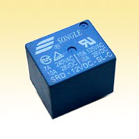
http://wiki.sunfounder.cc/images/1/1f/Relay_datasheet.pdf
[Top][Home]
Arduino and 4-Channel Relay Module
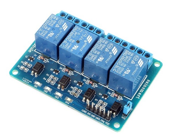
Source: https://cityos.io/tutorial/2017/Control-4-Channel-Relay-Module
[Top][Home]
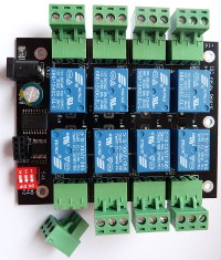
i2c Relay Modules
https://shop.controleverything.com/products/8-channel-relay-controller-i2c
[Top][Home]
Raspberry Pi and 8 Channel 5V Relay Module:
GPIO Pinouts:
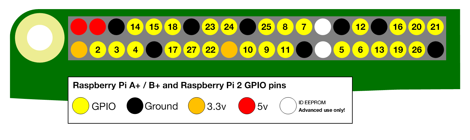
https://www.raspberrypi.org/documentation/usage/gpio/
https://pinout.xyz/pinout/pin5_gpio3
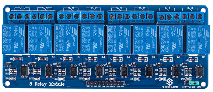
http://wiki.sunfounder.cc/index.php?title=8_Channel_5V_Relay_Module
Python Test propgram:
[Top][Home]
I2C Bi-directional Level Shifter
I2C bi-directional level shifter:
https://playground.arduino.cc/Main/I2CBi-directionalLevelShifter/
Sparkfun's Bi-Directional Logic Level Converter Hookup Guide:
https://learn.sparkfun.com/tutorials/bi-directional-logic-level-converter-hookup-guide
[Top][Home]
I2C RPi to Arduino UNO Communication
How Does It Work? Is It Safe?
The Raspberry Pi is running at 3.3 Volts while the Arduino is running at 5 Volts.
There are tutorials that suggest using a level converter for the I2C communication.
This is NOT needed if the Raspberry Pi is running as “master” and the Arduino is
running as “slave”.
The reason it works is because the Arduino does not have any pull-ups resistors
installed, but the P1 header on the Raspberry Pi has 1k8 ohms resistors to the
3.3 volts power rail. Data is transmitted by pulling the lines to 0v, for a
“high” logic signal. For “low” logic signal, it’s pulled up to the supply rail
voltage level. Because there is no pull-up resistors in the Arduino and because
3.3 volts is within the “low” logic level range for the Arduino everything works
as it should.
Source:
https://oscarliang.com/raspberry-pi-arduino-connected-i2c/
https://www.bluetin.io/interfacing/i2c-connect-raspberry-pi-arduino/
https://www.hackster.io/aardweeno/controlling-an-arduino-from-a-pi3-using-i2c-59817b
THIS METHOD DID NOT WORK!
Source:https://oscarliang.com/raspberry-pi-arduino-connected-i2c/
xxxxxxxxxxxxxxxxxxxxxxxxxxxxxxxxxxxxxxxxxxxx
Use This method to enable i2c bus on the RPi:
- Run sudo raspi-config.
- Use the down arrow to select 5 Interfacing Options
- Arrow down to P5 I2C.
- Select yes when it asks you to enable I2C
- Also select yes if it asks about automatically loading the kernel module.
- Use the right arrow to select the button.
- Select yes when it asks to reboot.
Source:https://learn.sparkfun.com/tutorials/raspberry-pi-spi-and-i2c-tutorial/#i2c-on-pi
[Top][Home]
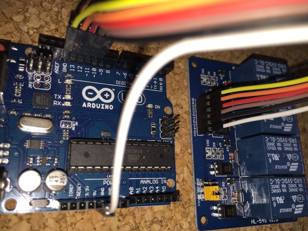
Patch Wiring Rpi to Arduino UNO
[Top][Home]
Confirming the i2c Device is Found
[Top][Home]
Wire Library
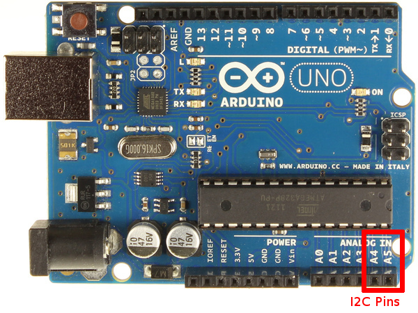
This library allows you to communicate with I2C / TWI devices. On the Arduino
boards with the R3 layout (1.0 pinout), the SDA (data line) and SCL (clock line)
are on the pin headers close to the AREF pin. The Arduino Due has two I2C / TWI
interfaces SDA1 and SCL1 are near to the AREF pin and the additional one is on
pins 20 and 21.
As a reference the table below shows where TWI pins are located on various Arduino boards.
| Board |
I2C / TWI pins |
| Uno, Ethernet |
A4 (SDA), A5 (SCL) |
| Mega2560 |
20 (SDA), 21 (SCL) |
| Leonardo |
2 (SDA), 3 (SCL) |
Due |
20 (SDA), 21 (SCL), SDA1, SCL1 |
https://www.arduino.cc/en/Reference/Wire
[Top][Home]
Useing the nano in place of the UNO
Single-Board-Computers/Arduino/Nano/Nano-V3.0-ATmega328P.html
[Top][Home]
Relay Conrtol with Node Red
Control I2C Relay Using Node-RED:
https://www.hackster.io/varuldcube100/control-i2c-relay-using-node-red-1a03f8
[Top][Home]
Similar Projects
Peter's DIY electronic projects - 8-channel I2C relay module:
http://jap.hu/electronic/relay_module_i2c.html
[Top][Home]
Glenn Lyons VK4PK
glenn@LyonsComputer.com.au
Ver:gnl20190501 - pre published v0.9