In a well designed power supply, there is plenty of isolation between the input
side of the supply and the output side.
On the input side, the earth terminal on the switch mode supply is connected to the metal frame work.
There is no connection between the primary and the secondary or the earthed case.
However, you can connect the outputs to obtain various common references:
`
The terminals that are connected together can be connected to the earth terminal
without issue and this then ground references the common terminals.
As the earth terminal is connected to the supply’s metal case when you mount it to
a metal enclosure and have the incoming mains lead earthed to the enclosure then
the supplies earths are automatically connected to each other and earthed to the
buildings earthing system.
If you get a tingle from the switch mode supplies DC output terminals and a
grounded enclosure then this indicates significant leakage between the AC side
of the supply and the secondary DC side.
You can measure this voltage with a LOW IMPEDANCE meter. Do NOT use a digital
meter as you will NOT get a true voltage measurement. You will find this voltage
measurement is a lot lower than you expect because of the very high source
impedance it is coming from. Connecting either the +ve or -ve terminal to the
ground terminal or earthed case should stop this.
Connecting it to the incoming neutral wire is DANGEROUS.
In the MEN system the neutral is connected to the earth steak at the switchboard,
all is ok and no problems should be encounter. However, what happens if you have
connected one of the DC terminals to the active conductor instead to the neutral conductor.
This can occur when the power point is wired incorrectly and someone has switched
the active and neutral conductors in the power point. The result could caue a fatality.
If the leakage through the power supply is enough to trip the earth leakage breaker
the the supply has suffered a catastrophic failure. It takes 30mA to activate the ELB.
Normal leakage to receive some sort of tingle needs only to be in the order of micro amps.
A lot of the time this is electrostatic coupling between primary and secondary of the
transformer. In high quality power transformers a metal shield between primary and secondary
winding's, that was connected to earth is used to prevent this from happening.
[Top][Home]
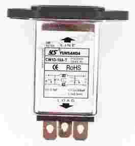
Addition common mode rejection can be achieved by winding about 10 loops
of the brown active (Line) and blue neutral wire, side by side (in parallel),
around a LO1238 toroidal core. This will require about 600mm of wire. This is
then connected immediately after the AC filter above.
[Top][Home]
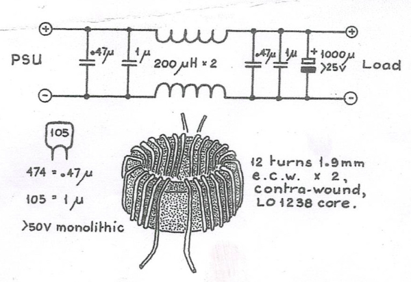
The filter coil is made from 12 turns of 1.0mm (16 AWG) enamelled Copper wire
for the negative and the positive legs, wound in opposite directions.
[Top][Home]